Table of Contents
Exam Summer Semester 2021
Additional permitted Aids
- non-programmable calculator,
- formulary (4 one-sided DIN A4 pages)
Hits
- The duration of the exam is 120 min.
- Attempts to cheat will lead to exclusion and failure of the exam.
- Withdrawal is no longer possible after these exam has been handed out.
- Please write down intermediate calculations and results on the assignment sheet. (when more space is needed also on the reverse side. In this case: Mark it clearly).
- Always use units in the calculation.
- Use a document-proof, non-red pen.
- Sub-tasks, which are independently solvable are marked with: (independent)
- Sub-tasks, which are hard are marked with: (hard)
Only EEE1-relevant Part
// //
1 Magnetic Field Lines
(written test, approx. 4 % of a 120-minute written test, SS2021)
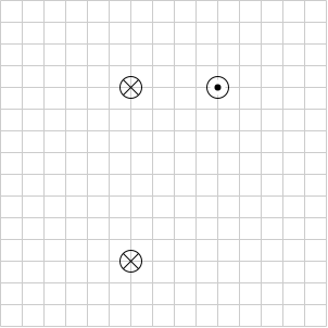
Several parallel conductors are projecting out of the plane.
The same current $|I|$ flows through all the conductors in different directions (see image below).
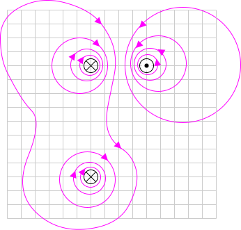
Sketch at least 10 field lines of the magnetic field strength $\vec{H}$ in such a way that the different properties of the field lines (e.g. direction and density) can be seen.
- high density of field lines near the conductors
- direction of the field lines given by the right-hand rule
- magnetic field has closed field lines
- resulting field given by superposition of field lines
1 Magnetic Flux Density
(written test, approx. 6 % of a 120-minute written test, SS2021)
An electric motor is operated for experiments in the laboratory. An alternating current with an amplitude of $\hat{I} = 100~\rm A$ is operated.
You stand next to it and think about whether you have any health problems to worry about. The figure below shows the top view of the laboratory with the supply line between $\rm A$ and $\rm B$.
$\mu_{0} = 4\pi\cdot 10^{-7} {{\rm Vs}\over{\rm Am}}$, $\mu_{r}=1$

a) What is the highest magnetic flux density through the line in your body? (3 points)
\begin{align*} H &= {{I}\over{2\pi \cdot r}} \end{align*}
The magnetic flux density $B$ is given as: $B = \mu_0 \mu_r H$
Here, the maximum current is $\hat{I} = 100~\rm A$ and the distance to the cable is $r = \sqrt{(0.1 {~\rm m})^2 + (0.4 {~\rm m})^2}= 0.412... ~\rm m$.
Therefore: \begin{align*} B &= 4\pi\cdot 10^{-7} {{\rm Vs}\over{\rm Am}} \cdot 1 \cdot {{100 ~\rm A}\over{2\pi \cdot 0.412... ~\rm m}} \end{align*}
b) The limit value for the magnetic flux density at the frequency used is $B_0 = 100~\rm \mu T$.
At what distance around the conductor is this value exceeded? (3 points, independent)
Again, the magnetic flux density $B$ is given as: $B = \mu_0 \mu_r H$
Therefore:
\begin{align*}
r &= \mu_0 \mu_r {{ I }\over{2\pi \cdot B}} \\
&= 4\pi\cdot 10^{-7} {{\rm Vs}\over{\rm Am}} {{100 ~\rm A}\over{2\pi \cdot 100\cdot 10^{-6} {~\rm T}}} \\
\end{align*}
1 Toroidal Coil
(written test, approx. 5 % of a 120-minute written test, SS2021)
A magnetic field with a flux density of at least $50 ~\rm mT$ is to be achieved in a ring-shaped coil (toroidal coil).
The coil has 60 turns, wound around soft iron with $\mu_{\rm r} = 1200$.
The average field line length in the coil should be $l = 12 ~\rm cm$.
$\mu_{0} = 4\pi\cdot 10^{-7} {{\rm Vs}\over{\rm Am}}$

What is the minimum current that must flow through a single winding?
\begin{align*} H &= {{N \cdot I}\over{l}} \end{align*}
Based on the flux density the magnetic field strength can be derived by $B = \mu_0 \mu_{\rm r} \cdot H$.
By this, the formula can be rearranged:
\begin{align*} H &= {{N \cdot I}\over{l}} \\ {{B}\over{ \mu_0 \mu_{\rm r}}} &= {{N \cdot I}\over{l}} \\ I &= {{B \cdot l}\over{ \mu_0 \mu_{\rm r} \cdot N}} \end{align*}
Putting in the numbers: \begin{align*} I &= {{ 0.05 {~\rm T} \cdot 0.12{~\rm m} }\over{ 4\pi\cdot 10^{-7} {{\rm Vs}\over{\rm Am}} \cdot 1'200 \cdot 60}} \\ &= 0.6631... {{\rm T\cdot m}\over{ {{\rm Vs}\over{\rm Am}} }} &= 0.6631... {{\rm {{\rm Vs}\over{\rm m^2}} \cdot m}\over{ {{\rm Vs}\over{\rm Am}} }} &= 0.6631... ~\rm A \end{align*}
1 Cylindrical Coil
(written test, approx. 6 % of a 120-minute written test, SS2021)
A cylindrical coil with the following information is given:
- Length $𝑙 = 30 {~\rm cm}$,
- Winding diameter $𝑑 = 390 {~\rm mm}$,
- Number of windings $𝑤 = 240$ ,
- Current through the conductor $𝐼 = 500 {~\rm mA}$,
- Material inside: Air
- $\mu_0 = 4\pi\cdot 10^{-7} {{\rm Vs}\over{\rm Am}}$
The proportion of the magnetic voltage outside the coil can be neglected. Determine the following for the inside of the coil:
a) the magnetic field strength (2 points)
Putting in the numbers: \begin{align*} H &= {{240 \cdot 0.5 {~\rm A}}\over{0.3 {~\rm m}}} \end{align*}
b) the magnetic flux density (2 points)
\begin{align*} B = \mu_0 \mu_{\rm r} H \end{align*}
Putting in the numbers: \begin{align*} B &= 4\pi\cdot 10^{-7} {{\rm Vs}\over{\rm Am}} \cdot 400 ~\rm {{A}\over{m}} \\ &= 0.0005026... {{\rm Vs}\over{\rm m^2}} \end{align*}
c) the magnetic flux (2 points)
\begin{align*} \Phi &= B \cdot A \end{align*}
Since the coil is cylindrical, the cross-sectional area is given as
\begin{align*} A = \pi r^2 = \pi \left( {{d}\over{2}} \right)^2 \end{align*}
Therefore: \begin{align*} \Phi &= B \cdot \pi \left( {{d}\over{2}} \right)^2 \end{align*}
Putting in the numbers: \begin{align*} \Phi &= 0.0005026... {{\rm Vs}\over{\rm m^2}} \cdot \pi \left( {{0.39{\rm m}}\over{2}} \right)^2 \\ &= 0.00006004... {\rm Vs} \end{align*}
1 effect of induction
(written test, approx. 5 % of a 120-minute written test, SS2021)
A single conductor loop is penetrated by a changing magnetic flux.
The following figure shows the variation of the flux $\Phi(t)$ over time.
Calculate the variation of the induced voltage $u_{\rm ind}(t)$ over time and draw it in a separate diagram.

For a linear function, the derivative can be substituted by Deltas ($\rm d \rightarrow \Delta$):
\begin{align*}
u_{\rm ind} = - {{ \Delta \Phi(t)}\over{ \Delta t}} = - { { \Phi(t_{\rm n+1} ) - \Phi(t_{\rm n} ) } \over { t_{\rm n+1} - t_{\rm n} } } \\
\end{align*}
For a piece-wise linear function, the induced voltage can be calculated for each interval.
Here, there are 5 different intervals - in the following called $\rm I$ to $\rm V$ from left to right:

- For the intervals $\rm I$, $\rm III$, and $\rm V$ , the flux $\Phi(t)$ is constant. Therefore, $\Delta \Phi(t)=0$ and $u_{\rm ind}(t)=0{~\rm V}$

- For the interval $\rm II$:
- The change in the flux is: $ \Delta \Phi(t) = 1.5 \cdot 10^{-4} {~\rm Vs} - 4.5 \cdot 10^{-4} {~\rm Vs}= - 3.0 \cdot 10^{-4} {~\rm Vs}$
- The time span is: $0.2 ~\rm s$
- Conclusively, the induced voltage is: $u_{\rm ind}(t) = + {{3.0 \cdot 10^{-4} {~\rm Vs}} \over {0.2 ~\rm s} } = 1.5 {~\rm mV}$

- For the interval $\rm IV$:
- The change in the flux is: $ \Delta \Phi(t) = 0 \cdot 10^{-4} {~\rm Vs} - 1.5 \cdot 10^{-4} {~\rm Vs}= - 1.5 \cdot 10^{-4} {~\rm Vs}$
- The time span is: $0.2 ~\rm s$
- Conclusively, the induced voltage is: $u_{\rm ind}(t) = + {{1.5 \cdot 10^{-4} {~\rm Vs}} \over {0.2 ~\rm s} } = 0.75 {~\rm mV}$


1 Coil in a magnetic Field
(written test, approx. 4 % of a 120-minute written test, SS2021)
A coil with $n = 300$ turns and a cross-sectional area $A = 600 ~\rm cm^2$ is located in a homogeneous magnetic field.
The rotation of the coil causes a sinusoidal change in the magnetic field in the coil with the frequency $f = 80~\rm Hz$.
The maximum value of the magnetic flux density in the coil is $\hat{B} = 2 \cdot 10^{-6} ~\rm {{Vs}\over{cm^2}}$.
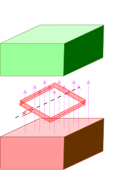
Derive the formula for the voltage induced in the coil and calculate the voltage amplitude.
\begin{align*} u_{\rm ind} &= - {{{\rm d}\Psi(t)}\over{{\rm d}t}} \\ &= - n{{{\rm d}\Phi(t)}\over{{\rm d}t}} \\ \end{align*}
With $\Phi(t)= B(t) \cdot A$, where $A$ is the constant area of a single winding and $B(t)$ is the changing field through this winding.
Due to the rotation, the field changes as:
\begin{align*} B(t) &= \hat{B} \cdot \sin(\omega t + \varphi) \\ &= \hat{B} \cdot \sin(2\pi f \cdot t + \varphi) \\ \end{align*}
This leads to: \begin{align*} u_{\rm ind} &= - n{{{\rm d}}\over{{\rm d}t}}A \hat{B} \cdot \sin(2\pi f \cdot t + \varphi) \\ &= - n \cdot A \hat{B} \cdot 2\pi f \cdot \cos(2\pi \cdot f t + \varphi) \\ \end{align*}
The absolute value of the factor in front of the $\cos$ is the maximum induced voltage $\hat{U}_{\rm ind}$: \begin{align*} \hat{U}_{\rm ind} &= n \cdot A \hat{B} \cdot 2\pi f \\ &= 300 \cdot 0.06{~\rm m^2} \cdot 2 \cdot 10^{-2} ~\rm {{Vs}\over{m^2}} \cdot 2\pi \cdot 80 {{1}\over{\rm s}} \\ &= 180.95... {~\rm m^2} \cdot {{\rm Vs}\over{\rm m^2}} \cdot {{1}\over{\rm s}} \\ &= 180.95... {~\rm V} \\ \end{align*}
1 Magnetic Voltage
(written test, approx. 6 % of a 120-minute written test, SS2021)
The following images show cross-sections of electrical cables.
A closed path is shown as a dashed line. The magnetic voltage $\theta$ on these paths shall be analyzed.
The following values are given for the currents:
- $I_1 = 5 {~\rm A}$
- $I_2 = 2 {~\rm A}$
- $I_3 = 1 {~\rm A}$
- $I_4 = 4 {~\rm A}$

Specify which magnetic voltages $\theta_{(1)}$, $\theta_{(2)}$, and $\theta_{(3)}$ result.
Note the direction of the path in each case!
- $I_{(1)} = +I_2 - I_1 - I_3 \quad \rightarrow \quad \theta_{(1)} = 2 {~\rm A} - 5 {~\rm A} - 1 {~\rm A} $
- $I_{(2)} = +I_3 + I_4 - I_1 \quad \rightarrow \quad \theta_{(2)} = 1 {~\rm A} + 4 {~\rm A} - 5 {~\rm A} $
- $I_{(3)} = +I_3 - I_4 - I_2 \quad \rightarrow \quad \theta_{(3)} = 1 {~\rm A} - 4 {~\rm A} - 2 {~\rm A} $
1 Lorentz Force (hard!)
(written test, approx. 10 % of a 120-minute written test, SS2021)
A $300 ~\rm km$ long, straight high-voltage direct current transmission line shall be analyzed. A current of $I = 1′200 ~\rm A$ flows through it.
A homogeneous geomagnetic field is assumed. The magnetic field strength has a vertical component of $B_{\rm v} = 40 ~\rm \mu T$ and a horizontal component of $B_{\rm h} = 20 ~\rm \mu T$.
The angle between the transmission line and the horizontal component of the field strength is $\alpha = 20°$.
The picture on the right shows the line (black), the field strength components, and the angle in front and top view for illustration purposes.

a) Calculate the force that results from the current flow on the entire conductor.
First, calculate the vertical and horizontal components and combine them accordingly.
Here, we have two components for the current - and therefore for the force - to evaluate.
Considering the right-hand rule (and the cross product), the vertical field $B_{\rm v}$ generates a horizontal force $F_{\rm h}$ and vice versa.
The horizontal component is given by

\begin{align*} F_{\rm h} &= I \cdot (l \cdot B_{\rm v}) \\ &= 1′200 {~\rm A} \cdot 300 \cdot 10^3{~\rm m} \cdot 40 \cdot 10^{-6}{~\rm {{Vs}\over{m²}}} \\ &= 14'400 ~\rm {{VAs}\over{m}} = 14'400 ~\rm {{Ws}\over{m}} = 14'400 ~\rm N \end{align*}
For the vertical component the angle &\alpha& has to be considered.
For the maximum $F_{\rm v}$ the angle &\alpha& has to be $90°$, therefore the $\sin$ has to be used.

\begin{align*} F_{\rm v} &= I \cdot l \cdot B_{\rm h} \cdot \sin\alpha \\ &= 1′200 {~\rm A} \cdot 300 \cdot 10^3{~\rm m} \cdot 40 \cdot 10^{-6}{~\rm {{Vs}\over{m²}}} \cdot \sin 20° \\ &= 2'462.545... ~\rm N \end{align*}
For the overall force $F$ the Pythagorean theorem has to be used:
\begin{align*} F &= \sqrt{F_{\rm v}^2 +F_{\rm h}^2} \\ &= \sqrt{({14'400 ~\rm N})^2 +({2'462.545... ~\rm N})^2} \\ &= 14'609.04... ~\rm N \end{align*}
b) The picture below shows the top view again. In which of the directions shown does the horizontal component $F_{\rm h}$ of the resulting force act? (Independent)

- The horizontal component $\vec{F}_{\rm h}$ of the force is based on the vertical component $\vec{B}_{\rm v}$ of the magnetic field.
- The vertical component $\vec{B}_{\rm v}$ of the magnetic field is not shown in the image but is pointing into the ground.
- It has to be perpendicular to $\vec{B}_{\rm v}$ and to $\vec{l}$. The right-hand rule has to be applied.
Full Exam
These is the full exam
- Full exam
-
1 Magnetic Field Lines
(written test, approx. 4 % of a 120-minute written test, SS2021)Several parallel conductors are projecting out of the plane.
The same current $|I|$ flows through all the conductors in different directions (see image below).
Sketch at least 10 field lines of the magnetic field strength $\vec{H}$ in such a way that the different properties of the field lines (e.g. direction and density) can be seen.
- high density of field lines near the conductors
- direction of the field lines given by the right-hand rule
- magnetic field has closed field lines
- resulting field given by superposition of field lines
1 Magnetic Flux Density
(written test, approx. 6 % of a 120-minute written test, SS2021)An electric motor is operated for experiments in the laboratory. An alternating current with an amplitude of $\hat{I} = 100~\rm A$ is operated.
You stand next to it and think about whether you have any health problems to worry about. The figure below shows the top view of the laboratory with the supply line between $\rm A$ and $\rm B$.$\mu_{0} = 4\pi\cdot 10^{-7} {{\rm Vs}\over{\rm Am}}$, $\mu_{r}=1$
a) What is the highest magnetic flux density through the line in your body? (3 points)
The magnetic field strength for a conducting wire is given as:\begin{align*} H &= {{I}\over{2\pi \cdot r}} \end{align*}
The magnetic flux density $B$ is given as: $B = \mu_0 \mu_r H$
Here, the maximum current is $\hat{I} = 100~\rm A$ and the distance to the cable is $r = \sqrt{(0.1 {~\rm m})^2 + (0.4 {~\rm m})^2}= 0.412... ~\rm m$.
Therefore: \begin{align*} B &= 4\pi\cdot 10^{-7} {{\rm Vs}\over{\rm Am}} \cdot 1 \cdot {{100 ~\rm A}\over{2\pi \cdot 0.412... ~\rm m}} \end{align*}
$B = 49 ~\mu \rm T$b) The limit value for the magnetic flux density at the frequency used is $B_0 = 100~\rm \mu T$.
At what distance around the conductor is this value exceeded? (3 points, independent)The formula for the magnetic field strength can be rearranged: \begin{align*} H &= {{I}\over{2\pi \cdot r}} \\ r &= {{I}\over{2\pi \cdot H}} \\ \end{align*}Again, the magnetic flux density $B$ is given as: $B = \mu_0 \mu_r H$
Therefore: \begin{align*} r &= \mu_0 \mu_r {{ I }\over{2\pi \cdot B}} \\ &= 4\pi\cdot 10^{-7} {{\rm Vs}\over{\rm Am}} {{100 ~\rm A}\over{2\pi \cdot 100\cdot 10^{-6} {~\rm T}}} \\ \end{align*}$r = 0.2~\rm m$1 Toroidal Coil
(written test, approx. 5 % of a 120-minute written test, SS2021)A magnetic field with a flux density of at least $50 ~\rm mT$ is to be achieved in a ring-shaped coil (toroidal coil).
The coil has 60 turns, wound around soft iron with $\mu_{\rm r} = 1200$.
The average field line length in the coil should be $l = 12 ~\rm cm$.$\mu_{0} = 4\pi\cdot 10^{-7} {{\rm Vs}\over{\rm Am}}$
What is the minimum current that must flow through a single winding?
The magnetic field strength of a toroidal coil is given as:\begin{align*} H &= {{N \cdot I}\over{l}} \end{align*}
Based on the flux density the magnetic field strength can be derived by $B = \mu_0 \mu_{\rm r} \cdot H$.
By this, the formula can be rearranged:\begin{align*} H &= {{N \cdot I}\over{l}} \\ {{B}\over{ \mu_0 \mu_{\rm r}}} &= {{N \cdot I}\over{l}} \\ I &= {{B \cdot l}\over{ \mu_0 \mu_{\rm r} \cdot N}} \end{align*}
Putting in the numbers: \begin{align*} I &= {{ 0.05 {~\rm T} \cdot 0.12{~\rm m} }\over{ 4\pi\cdot 10^{-7} {{\rm Vs}\over{\rm Am}} \cdot 1'200 \cdot 60}} \\ &= 0.6631... {{\rm T\cdot m}\over{ {{\rm Vs}\over{\rm Am}} }} &= 0.6631... {{\rm {{\rm Vs}\over{\rm m^2}} \cdot m}\over{ {{\rm Vs}\over{\rm Am}} }} &= 0.6631... ~\rm A \end{align*}
$I = 66 ~\rm mA$1 Cylindrical Coil
(written test, approx. 6 % of a 120-minute written test, SS2021)A cylindrical coil with the following information is given:
- Length $𝑙 = 30 {~\rm cm}$,
- Winding diameter $𝑑 = 390 {~\rm mm}$,
- Number of windings $𝑤 = 240$ ,
- Current through the conductor $𝐼 = 500 {~\rm mA}$,
- Material inside: Air
- $\mu_0 = 4\pi\cdot 10^{-7} {{\rm Vs}\over{\rm Am}}$
The proportion of the magnetic voltage outside the coil can be neglected. Determine the following for the inside of the coil:
a) the magnetic field strength (2 points)
\begin{align*} H &= {{N \cdot I}\over{l}} = {{w \cdot I}\over{l}} \end{align*}Putting in the numbers: \begin{align*} H &= {{240 \cdot 0.5 {~\rm A}}\over{0.3 {~\rm m}}} \end{align*}
$H = 400 ~\rm A/m$b) the magnetic flux density (2 points)
The magnetic field strength is $B = \mu_0 \mu_{\rm r} \cdot H$:\begin{align*} B = \mu_0 \mu_{\rm r} H \end{align*}
Putting in the numbers: \begin{align*} B &= 4\pi\cdot 10^{-7} {{\rm Vs}\over{\rm Am}} \cdot 400 ~\rm {{A}\over{m}} \\ &= 0.0005026... {{\rm Vs}\over{\rm m^2}} \end{align*}
$B = 0.50 ~\rm mT$c) the magnetic flux (2 points)
The magnetic flux is given as:\begin{align*} \Phi &= B \cdot A \end{align*}
Since the coil is cylindrical, the cross-sectional area is given as
\begin{align*} A = \pi r^2 = \pi \left( {{d}\over{2}} \right)^2 \end{align*}
Therefore: \begin{align*} \Phi &= B \cdot \pi \left( {{d}\over{2}} \right)^2 \end{align*}
Putting in the numbers: \begin{align*} \Phi &= 0.0005026... {{\rm Vs}\over{\rm m^2}} \cdot \pi \left( {{0.39{\rm m}}\over{2}} \right)^2 \\ &= 0.00006004... {\rm Vs} \end{align*}
$\Phi = 60 ~\rm \mu Wb$1 effect of induction
(written test, approx. 5 % of a 120-minute written test, SS2021)A single conductor loop is penetrated by a changing magnetic flux.
The following figure shows the variation of the flux $\Phi(t)$ over time.
Calculate the variation of the induced voltage $u_{\rm ind}(t)$ over time and draw it in a separate diagram.
Based on Faraday's Law of Induction the induced voltage is given by: \begin{align*} u_{\rm ind} =& - {{ {\rm d} }\over{ {\rm d}t}} \Psi(t) \bigg\rvert_{n=1}\\ =& - {{ {\rm d} }\over{ {\rm d}t}} \Phi(t) \\ \end{align*}For a linear function, the derivative can be substituted by Deltas ($\rm d \rightarrow \Delta$):
\begin{align*} u_{\rm ind} = - {{ \Delta \Phi(t)}\over{ \Delta t}} = - { { \Phi(t_{\rm n+1} ) - \Phi(t_{\rm n} ) } \over { t_{\rm n+1} - t_{\rm n} } } \\ \end{align*}For a piece-wise linear function, the induced voltage can be calculated for each interval.
Here, there are 5 different intervals - in the following called $\rm I$ to $\rm V$ from left to right:
- For the intervals $\rm I$, $\rm III$, and $\rm V$ , the flux $\Phi(t)$ is constant. Therefore, $\Delta \Phi(t)=0$ and $u_{\rm ind}(t)=0{~\rm V}$
- For the interval $\rm II$:
- The change in the flux is: $ \Delta \Phi(t) = 1.5 \cdot 10^{-4} {~\rm Vs} - 4.5 \cdot 10^{-4} {~\rm Vs}= - 3.0 \cdot 10^{-4} {~\rm Vs}$
- The time span is: $0.2 ~\rm s$
- Conclusively, the induced voltage is: $u_{\rm ind}(t) = + {{3.0 \cdot 10^{-4} {~\rm Vs}} \over {0.2 ~\rm s} } = 1.5 {~\rm mV}$
- For the interval $\rm IV$:
- The change in the flux is: $ \Delta \Phi(t) = 0 \cdot 10^{-4} {~\rm Vs} - 1.5 \cdot 10^{-4} {~\rm Vs}= - 1.5 \cdot 10^{-4} {~\rm Vs}$
- The time span is: $0.2 ~\rm s$
- Conclusively, the induced voltage is: $u_{\rm ind}(t) = + {{1.5 \cdot 10^{-4} {~\rm Vs}} \over {0.2 ~\rm s} } = 0.75 {~\rm mV}$
1 Coil in a magnetic Field
(written test, approx. 4 % of a 120-minute written test, SS2021)A coil with $n = 300$ turns and a cross-sectional area $A = 600 ~\rm cm^2$ is located in a homogeneous magnetic field.
The rotation of the coil causes a sinusoidal change in the magnetic field in the coil with the frequency $f = 80~\rm Hz$.
The maximum value of the magnetic flux density in the coil is $\hat{B} = 2 \cdot 10^{-6} ~\rm {{Vs}\over{cm^2}}$.
Derive the formula for the voltage induced in the coil and calculate the voltage amplitude.
The induced voltage $u_{\rm ind}$ is given by:\begin{align*} u_{\rm ind} &= - {{{\rm d}\Psi(t)}\over{{\rm d}t}} \\ &= - n{{{\rm d}\Phi(t)}\over{{\rm d}t}} \\ \end{align*}
With $\Phi(t)= B(t) \cdot A$, where $A$ is the constant area of a single winding and $B(t)$ is the changing field through this winding.
Due to the rotation, the field changes as:\begin{align*} B(t) &= \hat{B} \cdot \sin(\omega t + \varphi) \\ &= \hat{B} \cdot \sin(2\pi f \cdot t + \varphi) \\ \end{align*}
This leads to: \begin{align*} u_{\rm ind} &= - n{{{\rm d}}\over{{\rm d}t}}A \hat{B} \cdot \sin(2\pi f \cdot t + \varphi) \\ &= - n \cdot A \hat{B} \cdot 2\pi f \cdot \cos(2\pi \cdot f t + \varphi) \\ \end{align*}
The absolute value of the factor in front of the $\cos$ is the maximum induced voltage $\hat{U}_{\rm ind}$: \begin{align*} \hat{U}_{\rm ind} &= n \cdot A \hat{B} \cdot 2\pi f \\ &= 300 \cdot 0.06{~\rm m^2} \cdot 2 \cdot 10^{-2} ~\rm {{Vs}\over{m^2}} \cdot 2\pi \cdot 80 {{1}\over{\rm s}} \\ &= 180.95... {~\rm m^2} \cdot {{\rm Vs}\over{\rm m^2}} \cdot {{1}\over{\rm s}} \\ &= 180.95... {~\rm V} \\ \end{align*}
\begin{align*} u_{\rm ind} = - 181 {~\rm V} \cdot \cos(503 {{1}\over{\rm s}} \cdot t ) \\ \end{align*}1 Magnetic Voltage
(written test, approx. 6 % of a 120-minute written test, SS2021)The following images show cross-sections of electrical cables.
A closed path is shown as a dashed line. The magnetic voltage $\theta$ on these paths shall be analyzed.
The following values are given for the currents:- $I_1 = 5 {~\rm A}$
- $I_2 = 2 {~\rm A}$
- $I_3 = 1 {~\rm A}$
- $I_4 = 4 {~\rm A}$
Specify which magnetic voltages $\theta_{(1)}$, $\theta_{(2)}$, and $\theta_{(3)}$ result.
Note the direction of the path in each case!For the resulting current the direction of the path has to be considered with the right-hand rule:- $I_{(1)} = +I_2 - I_1 - I_3 \quad \rightarrow \quad \theta_{(1)} = 2 {~\rm A} - 5 {~\rm A} - 1 {~\rm A} $
- $I_{(2)} = +I_3 + I_4 - I_1 \quad \rightarrow \quad \theta_{(2)} = 1 {~\rm A} + 4 {~\rm A} - 5 {~\rm A} $
- $I_{(3)} = +I_3 - I_4 - I_2 \quad \rightarrow \quad \theta_{(3)} = 1 {~\rm A} - 4 {~\rm A} - 2 {~\rm A} $
\begin{align*} \theta_{(1)} &= -4 {~\rm A} \\ \theta_{(2)} &= 0 {~\rm A} \\ \theta_{(3)} &= -5 {~\rm A} \\ \end{align*}1 Lorentz Force (hard!)
(written test, approx. 10 % of a 120-minute written test, SS2021)A $300 ~\rm km$ long, straight high-voltage direct current transmission line shall be analyzed. A current of $I = 1′200 ~\rm A$ flows through it.
A homogeneous geomagnetic field is assumed. The magnetic field strength has a vertical component of $B_{\rm v} = 40 ~\rm \mu T$ and a horizontal component of $B_{\rm h} = 20 ~\rm \mu T$.
The angle between the transmission line and the horizontal component of the field strength is $\alpha = 20°$.
The picture on the right shows the line (black), the field strength components, and the angle in front and top view for illustration purposes.
a) Calculate the force that results from the current flow on the entire conductor.
First, calculate the vertical and horizontal components and combine them accordingly.The force on the transmission line can be calculated via the Lorentz force $\vec{F}_\rm L$: \begin{align*} \vec{F} = I \cdot (\vec{l} \times \vec{B}) \end{align*}Here, we have two components for the current - and therefore for the force - to evaluate.
Considering the right-hand rule (and the cross product), the vertical field $B_{\rm v}$ generates a horizontal force $F_{\rm h}$ and vice versa.The horizontal component is given by
\begin{align*} F_{\rm h} &= I \cdot (l \cdot B_{\rm v}) \\ &= 1′200 {~\rm A} \cdot 300 \cdot 10^3{~\rm m} \cdot 40 \cdot 10^{-6}{~\rm {{Vs}\over{m²}}} \\ &= 14'400 ~\rm {{VAs}\over{m}} = 14'400 ~\rm {{Ws}\over{m}} = 14'400 ~\rm N \end{align*}
For the vertical component the angle &\alpha& has to be considered.
For the maximum $F_{\rm v}$ the angle &\alpha& has to be $90°$, therefore the $\sin$ has to be used.
\begin{align*} F_{\rm v} &= I \cdot l \cdot B_{\rm h} \cdot \sin\alpha \\ &= 1′200 {~\rm A} \cdot 300 \cdot 10^3{~\rm m} \cdot 40 \cdot 10^{-6}{~\rm {{Vs}\over{m²}}} \cdot \sin 20° \\ &= 2'462.545... ~\rm N \end{align*}
For the overall force $F$ the Pythagorean theorem has to be used:
\begin{align*} F &= \sqrt{F_{\rm v}^2 +F_{\rm h}^2} \\ &= \sqrt{({14'400 ~\rm N})^2 +({2'462.545... ~\rm N})^2} \\ &= 14'609.04... ~\rm N \end{align*}
$F = 14'609 ~\rm N$b) The picture below shows the top view again. In which of the directions shown does the horizontal component $F_{\rm h}$ of the resulting force act? (Independent)
- The horizontal component $\vec{F}_{\rm h}$ of the force is based on the vertical component $\vec{B}_{\rm v}$ of the magnetic field.
- The vertical component $\vec{B}_{\rm v}$ of the magnetic field is not shown in the image but is pointing into the ground.
- It has to be perpendicular to $\vec{B}_{\rm v}$ and to $\vec{l}$. The right-hand rule has to be applied.
Only option $7.$ is perpendicular to $\vec{B}_{\rm v}$ and to $\vec{l}$ and points in the right direction by the right-hand rule.1 Impedance Characteristics
(written test, approx. 6 % of a 120-minute written test, SS2021)A coil has an inductive reactance of $X_0 = X(f_0) = 80~\rm \Omega$ at a frequency $f_0 = 60 ~\rm kHz$.
Calculate the frequencies $f_1$, $f_2$, $f_3$ at which the following reactances are measured:
- $X_1 = 50 ~\rm \Omega$
- $X_2 = 121 ~\rm \Omega$
- $X_3 = 147 ~\rm \Omega$
There are multiple ways to solve this question.
One way would be, to calculate the inductance $L$ first by rearranging $X(f) = 2\pi \cdot f \cdot L$.
Another way uses ratios (or “rule of three”), since $X(f) = f \cdot k$ with a constant $k$.
Therefore one can set up two formulas $X_n = f_n \cdot k$, $X_0 = f_0 \cdot k$, and divide the formulae by each other.
This leads to: \begin{align*} {{X_n}\over{X_0}} &= {{f_n}\over{f_0}} \\ f_n &= {{X_n}\over{X_0}}\cdot f_0 = {{f_0}\over{X_0}}\cdot X_n \\ \end{align*}Putting in the numbers: \begin{align*} f_n &= {{60 ~\rm kHz}\over{80~\rm \Omega}}\cdot X_n \\ &= 0.75 {{\rm \Omega}\over{\rm kHz}}\cdot X_n \\ \end{align*}
- $f_1 = 37.5~\rm kHz$
- $f_2 = 90.75~\rm kHz$
- $f_3 = 110.25~\rm kHz$
1 Complex series circuit
(written test, approx. 8 % of a 120-minute written test, SS2021)A series circuit of $C = 4.95~\rm nF$, $R = 200 ~\rm \Omega$ at $f = 40 ~\rm kHz$ shall be given.
a) Determine the complex impedance $\underline{Z}_C$.
The complex impedance $\underline{Z}_C$ is given as \begin{align*} \underline{Z}_C &= {{1}\over{{\rm j} \cdot 2\pi \cdot f \cdot C }} \\ &= {{-{\rm j}}\over{2\pi \cdot 40 \cdot 10^3 ~\rm Hz \cdot 4.95 \cdot 10^{-9} ~\rm F }} \\ &= -{\rm j} \cdot 803.81... ~\rm \Omega \\ \end{align*}$\underline{Z}_C = -{\rm j} \cdot 804 ~\rm \Omega $b) Determine the absolute value of the resulting impedance of the series circuit using an impedance vector diagram. Pay attention to the correct dimensioning.

Based on the diagram: $|\underline{Z}|= 828 ~\Omega$
1 Component Parameters
(written test, approx. 10 % of a 120-minute written test, SS2021)The equivalent circuit diagram of an electric motor represents a resistive-inductive load.
The values of the series resistance $R_{\rm M}$ and the inductance $L_{\rm M}$ are to be determined below. Both result in the impedance of the motor.a) Derive in general the equation for the absolute value of the impedance of the motor.
The complex impedance $\underline{Z}$ for a resistive-inductive load (=$R$-$L$ series circuit) is given as \begin{align*} \underline{Z} &= {\rm j} \cdot X_L + R_{\rm M} \\ &= {\rm j} \cdot 2\pi \cdot f \cdot L_{\rm M} + R_{\rm M} \\ \end{align*}The Pythagorean theorem can derive the absolute value: \begin{align*} |\underline{Z}|&= \sqrt{ (2\pi \cdot f \cdot L_{\rm M})^2 + R_{\rm M}^2 }\\ \end{align*}
\begin{align*} Z = \sqrt{ (2\pi \cdot f \cdot L_{\rm M})^2 + R_{\rm M}^2 } \end{align*}
For the next exercises consider the following:
In two measurements, an AC voltage with a constant RMS value of $U = U_1 = U_2 = 50 ~\rm V$ but two different frequencies, $f_1$ and $f_2$ was applied.
This resulted in the recorded current of- for $f_1 = 50 ~\rm Hz$: $I_1 = 8~\rm A$
- for $f_2 = 100~\rm Hz$: $I_2 = 5~\rm A$
b) Determine the absolute values of the impedances from the specified RMS values at $f_1$ and $f_2$ (independent).
The absolute value of the impedance is given as $Z = {{U}\over{I}}$.
This leads to:- $Z_1 = {{U_1}\over{I_1}} = {{50 ~\rm V}\over{8~\rm A}} $
- $Z_2 = {{U_2}\over{I_2}} = {{50 ~\rm V}\over{5~\rm A}}$
- $Z_1 = 6.25~\rm \Omega$
- $Z_2 = 10~\rm \Omega$
c) Determine the component parameters $R_{\rm M}$ and $L_{\rm M}$ from a) and b)! (hard).
Since we have $Z_1$ and $Z_2$ from b) we can subtract two of the formulas from a).
This has the advantage that $R_{\rm M}$ will cancel out: \begin{align*} Z_2^2 - Z_1^2 &= (2\pi \cdot f_2 \cdot L_{\rm M})^2 + R_{\rm M}^2 - \left( (2\pi \cdot f_1 \cdot L_{\rm M})^2 + R_{\rm M}^2 \right) \\ &= (2\pi \cdot f_2 )^2 \cdot L_{\rm M}^2 - (2\pi \cdot f_1)^2 \cdot L_{\rm M}^2 \\ \end{align*}Now we can rearrange to $L_{\rm M}^2$:
\begin{align*} Z_2^2 - Z_1^2 &= L_{\rm M}^2 \cdot \left( (2\pi \cdot f_2 )^2 - (2\pi \cdot f_1)^2 \right) \\ L_{\rm M}^2 &= {{Z_2^2 - Z_1^2} \over { (2\pi \cdot f_2 )^2 - (2\pi \cdot f_1)^2 }} \\ L_{\rm M}^2 &= {{Z_2^2 - Z_1^2} \over { (2\pi)^2 \cdot ( f_2^2 - f_1^2 ) }} \\ \end{align*}
And then to $L_{\rm M}$:
\begin{align*} L_{\rm M} &={{1}\over{2\pi}} \sqrt{{{Z_2^2 - Z_1^2} \over { f_2^2 - f_1^2 }} }\\ \end{align*}
With the values:
\begin{align*} L_{\rm M} &={{1}\over{2\pi}} \sqrt{{{(10~\Omega)^2 - (6.25~\Omega)^2} \over { (100 {{1}\over{s}})^2 - (50 {{1}\over{s}})^2 }} }\\ &=14.346... ~\rm mH\\ \end{align*}
The resistance value $R_{\rm M}$ can be derived from \begin{align*} Z_2^2 &= (2\pi \cdot f_2 \cdot L_{\rm M})^2 + R_{\rm M}^2 \\ R_{\rm M}^2 &= Z_2^2 - (2\pi \cdot f_2 \cdot L_{\rm M})^2 \\ R_{\rm M} &=\sqrt{ Z_2^2 - (2\pi \cdot f_2 \cdot L_{\rm M})^2}\\ \end{align*}
The values have to be inserted also for $R_{\rm M}$: \begin{align*} R_{\rm M} &=\sqrt{ (10~\rm \Omega)^2 - (2\pi \cdot 100 {{1}\over{s}} \cdot 0.014346... ~\rm H)^2}\\ &= 4.3301...~\Omega \end{align*}
- $R_{\rm M} = 4.33 ~\Omega$
- $L_{\rm M} = 14.35 ~\rm mH$
1 Signal Analysis
(written test, approx. 6 % of a 120-minute written test, SS2021)At an AC consumer, the following functions for voltage and current were measured:
- $u(t) = 50{~\rm V} \cdot \cos (6000 {{1}\over{\rm s}} \cdot t + 4) $
- $i(t) = 30{~\rm A} \cdot \sin (6000 {{1}\over{\rm s}} \cdot t + 5) $
a) Determine the amplitude values $\hat{U}$, $\hat{I}$ and the RMS values $U$, $I$
- The amplitude values $\hat{U}$, $\hat{I}$ are given directly by the coefficient of the cosine and sine functions
- For the RMS values of sinusoidal functions the amplitudes have to be multiplied with ${{1}\over{2}}\sqrt{2}$
Amplitude values:- $\hat{U} = 50{~\rm V}$
- $\hat{I} = 30{~\rm A}$
RMS values:
- $U = 35.4{~\rm V}$
- $I = 21.2{~\rm A}$
b) Determine the frequency $f$ and the phase angle $\varphi$ in degrees (°). (Independent)
The frequency can be derived by the term in the sine function: \begin{align*} \omega &= 6000 {{1}\over{\rm s}} \\ 2\pi \cdot f &= 6000 {{1}\over{\rm s}} \\ f &= {{6000}\over{2\pi}} {{1}\over{\rm s}} \\ f &= 954.93... ~\rm Hz \\ \end{align*}For the phase $\varphi$, we have to subtract $\varphi_i $ from $\varphi_u$.
But to get these values, both the $u(t)$ and $i(t)$ need to have the same sinusoidal function! Therefore:- $\varphi_i = 5$
- $\varphi_u = 4 + {{\pi}\over{2}}$
By this we get for $\varphi$ \begin{align*} \varphi &= \varphi_u - \varphi_i \\ &= 4 + {{\pi}\over{2}} - 5 \\ &= 2.14159... \\ \end{align*}
Converted in degree: \begin{align*} \varphi &= 2.14159... \cdot {{360°}\over{2\pi}} \\ &= 32.7042...° \\ \end{align*}
- $f = 955 ~\rm Hz$
- $\varphi = +32.7°$
c) Is the measured element resistive-capacitive or resistive-inductive?
The quantities are available in the consumer arrow system. (hard)The phase shift is positive - therefore, the element is resistive-inductive.1 Resonant Circuit
(written test, approx. 4 % of a 120-minute written test, SS2021)Given a resonant circuit, that is fed by a linear voltage source (circuit diagram on the right).
The inductance $L$ and capacitance $C$ are fixed. The resistance $R$ can be varied.- $u_{\rm s} = 12{~\rm V} \cdot \sin (2 \pi \cdot f_0 \cdot t) $
- $R_i = 200~\rm m\Omega$
- $L = 20~\rm mH$
- $C = 30~\rm \mu F$

a) What is the resonance frequency $f_0$?
The resonant frequency $f_0$ is given as \begin{align*} f_0 = {{1}\over{ 2\pi \sqrt{LC} }} \end{align*}With the values: \begin{align*} f_0 &= {{1}\over{ 2\pi \sqrt{20 \cdot 10^{-3} ~\rm H \cdot 30 \cdot 10^{-6} ~\rm F} }} \\ &= 205.4681... \rm Hz \end{align*}
$f_0 = 205.5 \rm Hz$b) How large must $R$ be, so that at resonance the voltage across the capacitor is $U_C = 4 \cdot U_{\rm s}$? (independent)
For the following calculation, the internal resistance $R_i$ and the resistance $R$ have to be combined: \begin{align*} R_\Sigma = R_i + R \\ \end{align*}Here, either one knows that the gain factor $Q$ stands for $Q={{U_C}\over{U_{\rm s}}}$ and therefore can directly use the following formula: \begin{align*} Q = {{U_C}\over{U_{\rm s}}} &= {{1}\over{R_\Sigma}} \sqrt{ {{L}\over{C}} } \\ R_\Sigma &= {{U_{\rm s}}\over{U_C}} \sqrt{ {{L}\over{C}} } \\ \end{align*}
When the gain factor is not known, one has to derive it:
The voltage $I$ at resonance is only given by the total ohmic resistance $R_\Sigma$ and the source voltage $U_{\rm s}$: \begin{align*} I = {{U_{\rm s}}\over{R_\Sigma}} \end{align*}This current flow also through the impedance of the capacitor \begin{align*} U_C &= Z_C \cdot I \\ &= {{1}\over{\omega C}} \cdot I \\ &= {{U_{\rm s}}\over{\omega C R_\Sigma }} \\ \end{align*}
At resonance, the angular frequency $\omega$ is given by $\omega= {{1}\over{\sqrt{LC}}}$.
\begin{align*} U_C &= {{U_{\rm s}}\over{{{1}\over{\sqrt{LC}}} C R_\Sigma }} \\ &= {{U_{\rm s}}\over{\sqrt{{{C}\over{L}}} R_\Sigma }} \\ &= {{U_{\rm s}}\over{R_\Sigma }} \sqrt{{{L}\over{C}}} \\ \end{align*}In both cases, we end up with the same formula, where we have to insert the physical values: \begin{align*} R_\Sigma &= {{U_{\rm s}}\over{U_C}} \sqrt{ {{L}\over{C}} } \\ &= {{1}\over{4}} \sqrt{ {{20\cdot 10^{-3} ~\rm H}\over{30\cdot 10^{-6} ~\rm C}} } \\ &= 6.4549...~\Omega \\ \end{align*}
And so, the resistance $R$ is: \begin{align*} R &= R_\Sigma - R_i \\ &= 6.4549...~\Omega - 0.2~\Omega \\ &= 6.2549...~\Omega \end{align*}
$R = 6.255~\Omega$1 Multiphase systems
(written test, approx. 4 % of a 120-minute written test, SS2021)A symmetrical three-phase generator in a delta connection shall be considered in the following.
A voltage with the RMS value $U_{\rm RMS} = 110~\rm V$ is applied between the terminals of each winding.
Through each of the windings, there is a current with an RMS value $I_{\rm RMS} = 5 ~\rm A$ and a phase shift of $\varphi = +25°$ compared to the voltage.a) Draw the circuit diagram.

b) Specify the RMS value of the phase voltage $U_\rm L$ and the string voltage $U_\rm S$.
Since the given voltage of $U_{\rm RMS} = 110~\rm V$ is applied between the terminals of each winding, this is also the string voltage $U_\rm S$.
For delta configuration, the phase voltage $U_\rm L$ is equal to the string voltage $U_\rm S$.
- $U_{\rm S} = 110~\rm V$
- $U_{\rm L} = 110~\rm V$
c) Specify the RMS value of the phase current $I_\rm L$ and the string current $I_\rm S$.
Since the given current of $I_{\rm RMS} = 5~\rm A$ is running through each winding, this is also the string current $I_\rm S$.
For the phase current $I_\rm L$, one has to consider that at each node the sum of all the notes must be zero: $\sum_i I_i =0$.
By this (and showing in the example in the image below), One can see, that $I_\rm L= \sqrt{3} \cdot I_{\rm RMS} = \sqrt{3} \cdot 5~\rm A$
- $I_{\rm S} = 5~\rm A$
- $I_{\rm L} = 8.66~\rm A$
d) Determine the active power.
The active power $P$ is given by: $P = 3 \cdot U \cdot I \cdot \sin(\varphi)$ \begin{align*} P &= 3 \cdot 110{~\rm V} \cdot 5{~\rm A} \cdot \sin(25°) \\ &= 1'610.888... ~\rm W \end{align*}$W = 1.61 ~\rm kW$