1 Complex voltage dividers
(written test, approx. 16 % of a 60-minute written test, SS2023)
The circuit below shall be given with the following values:
- $R = 1.1 ~\rm k\Omega$
- $L = 3.5 ~\rm mH$
- $\underline{U}_\rm I = 5 ~\rm V$
- $f_0 = 150 ~\rm kHz$
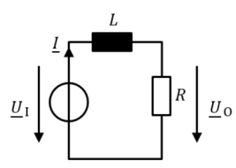
1. Calculate the impedance $\underline{Z}_L$.
\begin{align*}
\underline{Z}_L &= {\rm j} \cdot \omega \cdot L \\
&= {\rm j} \cdot 2\pi \cdot 150 ~\rm kHz \cdot 3.5 ~\rm mH
\end{align*}
\begin{align*}
\underline{Z}_L &= {\rm j}\cdot 3.3 ~\rm k\Omega
\end{align*}
2. Draw the two impedance phasors and the resulting phasor for the overall impedance in a diagram. Choose an appropriate scaling factor and write it down.

3. Calculate the output voltage $|\underline{U}_\rm O|$ and the phase shift between $\underline{U}_\rm O$ and $\underline{U}_\rm I$.
The formula to start with is the (complex) voltage divider:
\begin{align*}
\underline{U}_{\rm O} &= \underline{U}_{\rm I} \cdot {{R} \over {R+{\rm j}\cdot Z_L }} \\
&= \underline{U}_{\rm I} \cdot {{R} \over {R+{\rm j}\cdot Z_L }} \cdot {{R-{\rm j}\cdot Z_L} \over {R-{\rm j}\cdot Z_L }}\\
\end{align*}
\begin{align*}
\underline{U}_{\rm O} &= 0.5 ~\rm V - j \cdot 1.5 ~V
\end{align*}
4. Calculate the cut-off frequency of this setup.
At cut off frequency the absolute values of impedances $\underline{Z}_L$ is equal to $\underline{Z}_R=R$. This leads to:
\begin{align*}
f_{\rm cutoff} &= {{R} \over {2\pi \cdot L} } \\
&= {{1.1 \cdot 10^3 {\rm {V} \over{A} } } \over {2\pi \cdot 3.5 \cdot 10^{-3} {\rm {As} \over{V} } }}
\end{align*}
\begin{align*}
f_{\rm cutoff} &= 50 ~\rm kHz
\end{align*}