This is an old revision of the document!
Exam Summer Semester 2021
Additional permitted Aids
- non-programmable calculator,
- formulary (4 one-sided DIN A4 pages)
Hits
- The duration of the exam is 120 min.
- Attempts to cheat will lead to exclusion and failure of the exam.
- Withdrawal is no longer possible after these exam has been handed out.
- Please write down intermediate calculations and results on the assignment sheet. (when more space is needed also on the reverse side. In this case: Mark it clearly).
- Always use units in the calculation.
- Use a document-proof, non-red pen.
- Sub-tasks, which are independently solvable are marked with: (independent)
- Sub-tasks, which are hard are marked with: (hard)
Tasks
Exercise E9
Charging Capacitors
(written test, approx. 16 % of a 60-minute written test, WS2022)
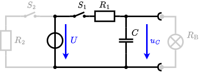
The circuit shown in the following is used to control the brightness when turning on a small light bulb.

The circuit contains a voltage source $U=12 ~\rm{V}$, a switch $S_1$, a resistor of $R_1=20 ~\Omega$ and a capacitor of $C=100 ~\rm{µF}$.
The switch $S_2$ to an additional consumer $R_2$ will be considered to be open for the first tasks. At the moment $t_0=0 ~\rm{s}$ the switch $S_1$ is closed, the voltage across the capacitor is $u_c (t_0 )=0 ~\rm{V}$.
1. First do not consider the light bulb – it is not connected to the RC circuit.
Calculate the point of time $t_1$ when $u_c (t_1)=0.5\cdot U$.
So, here only R_1 and C gives the time constant: $\tau = R_1 \cdot C$
The following formula describes the time course of $u_C(t)$ which has to be $u_c (t_1)=0.5\cdot U$: \begin{align*} u_c (t) = U \cdot (1- e^{t/\tau}) = 0.5\cdot U \end{align*} It has to be rearranged to $t$ \begin{align*} (1- e^{t/\tau}) &= 0.5 \\ e^{t/\tau} &= 0.5 \\ t/\tau &= ln(0.5) \\ t &= \tau \cdot ln(0.5) \\ t &= R_1 \cdot C \cdot ln(0.5) \end{align*}
2. Calculate the overall energy dissipated by $R_1$ while charging the capacitor $0 ~\rm{V}$ to $12 ~\rm{V}$.
3. Now, consider the light bulb as a resistor of $R_\rm B=20 ~\Omega$, and ignore again the left side ($S_2$ is open).
The voltage across the capacitor is again $0 ~\rm{V}$ at the moment $t_0=0 ~\rm{s}$ when the switch $S_1$ is closed.
Calculate the voltage $u_c (t_2)$ across the capacitor at $t_2=1 ~\rm{ms}$ after closing the switch.
Hint: To solve this, first create an equivalent linear voltage source from $U$, $R_1$, and $R_\rm B$.
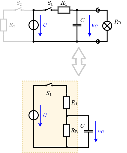
An equivalent linear voltage source can be given with $U$, $R_1$, and $R_\rm B$ as seen in yellow.
Therefore, the voltage of the equivalent linear voltage source is: $U_s = U \cdot {{R_\rm B}\over{R_1 + R_\rm B}} = 1/2 \cdot U$
The internal resistance is given by substituting the ideal voltage source with its resistance ($=0 ~\Omega$, short-circuit).
\begin{align*}
R_i &= R_1 || R_\rm B \\
&= 10 ~\Omega
\end{align*}
\begin{align*} u_c (t_2) &= U_s \cdot (1- e^{t_2/(R_i\cdot C)}) \\ &= {{1}\over{2}} \cdot U \cdot (1- e^{1~\rm{ms}/(10 ~\Omega \cdot 100 ~\rm{µF})}) \end{align*}
4. Explain (without calculation) how the situation in 3. would change once also $S_2$ is closed from the beginning on.
On an alternative view, one can try to create an equivalent linear voltage source again. Then, the internal resistance is given by substituting the ideal voltage source is again short-circuiting $R_2$.
Exercise E13 Impedances at different Frequencies
(written test, approx. 18 % of a 60-minute written test, WS2022)
Calculate the resistor values which have to be used in the following circuits.
1. A resistor $R_1$ shall have the same absolute value of the impedance as a capacitor $C_1=40 ~{\rm nF}$ at $f_1=4 ~{\rm MHz}$.
\begin{align*} R_1 &= |\underline{X}_{C1}| \\ &= {{1}\over{2\pi \cdot f \cdot C_1}} \\ &= {{1}\over{2\pi \cdot 4 ~{\rm MHz} \cdot 40 ~\rm nF}} \\ \end{align*}
2. A $RL$ series circuit with $L_2=4.7 ~\rm µH$, where an AC voltage source of $U_2=1.0 ~\rm V$ with $f_2=450 ~\rm kHz$ generates a current $I_2=60 ~\rm mA$.
The equivalent impedance for $R$ and $L$ combined is given by \begin{align*} {{\underline{U}}\over{\underline{I}}} &= R_2 + \underline{X}_{L2} \\ &= R_2 + {\rm j} \cdot \omega L \end{align*} Since ${\rm j} \cdot \omega L $ is perpendicular to $R_2$ this can be simplified to: \begin{align*} \left| {{\underline{U}}\over{\underline{I}}} \right|^2 &= |R_2|^2 + |\underline{X}_{L2}|^2 \\ \left( {{U}\over{I}} \right)^2 &= {R_2}^2 + {X_{L2}}^2 \\ \end{align*}
This can be rearranged to get $R_2$: \begin{align*} R_2 &= \sqrt{ \left( {{U }\over{I }} \right)^2 - X_{L2}^2 } \\ &= \sqrt{ \left( {{1~{\rm V}}\over{60~\rm mA}} \right)^2 - (2\pi \cdot 450~{\rm kHz} \cdot 4.7 ~ {\rm µH})^2 } \\ \end{align*}
\begin{align*} R_2 &= 10.0 ~\Omega \\ \end{align*}
3. A $RC$ parallel circuit with $C_3=4.7 ~\rm nF$ on an AC current source ($I_{3S}=1.3 ~\rm A$,$f_3=200 ~\rm kHz$), which generates a current of $I_{3R}=1.0 ~\rm A$ through $R_3$.
Parallel circuit means that the voltage is the same on $R_3$ and $C_3$:
\begin{align*}
\underline{U}_3 = R_3 \cdot \underline{I}_{3R} = -{\rm j}\cdot {X}_{3C} \cdot \underline{I}_{3C}
\end{align*}
So it gets clear, that $\underline{I}_{3R}$ is perpendicular to $\underline{I}_{3C}$ (It has to, since $R_3$ is perpendicular to $-{\rm j}\cdot {X}_{3C}$, too).
Therefore, the resulting current of the parallel circuit is given as:
\begin{align*}
\underline{I}_{3} &= \underline{I}_{3R} + \underline{I}_{3C} \\
|\underline{I}_{3}|^2 &= |\underline{I}_{3R}|^2 + |\underline{I}_{3C}|^2 \\
{I}_{3C} &= \sqrt{|{I}_{3}|^2 - |{I}_{3R}|^2}
\end{align*}
Back to the first formula: \begin{align*} R_3 \cdot {I}_{3R} &= {X}_{3C} \cdot {I}_{3C} \\ R_3 &= {X}_{3C} \cdot {{{I}_{3C}}\over{{I}_{3R}}} \\ &= {{1}\over{2\pi \cdot f \cdot C_3}} \cdot {{\sqrt{|{I}_{3}|^2 - |{I}_{3R}|^2}}\over{{I}_{3R}}} \\ \end{align*}
\begin{align*} R_3 &= 70.0 ~\Omega \\ \end{align*}
Exercise E11 Analyzing complex Impedances
(written test, approx. 14 % of a 60-minute written test, WS2022)
A circuit with an ideal voltage source ($U=50 ~\rm V$, $f=330 ~\rm Hz$) and two components ($R$ and $\underline{X}_1$) shall be given.
After analysis, the following formula for the impedance was extracted:
\begin{align*}
\underline{Z} = \left({{2}\over{3+4{\rm j}}}+5{\rm j} \right) \Omega
\end{align*}
1. Calculate the physical values of the two components.
\begin{align*} \underline{Z} &= \left({{2}\over{3+4{\rm j}}} + 5{\rm j} \right) ~\Omega \\ &= \left({{2}\over{3+4{\rm j}}} \cdot {{3-4{\rm j}}\over{3-4j}} + 5{\rm j} \right) ~\Omega \\ &= \left({{2}\over{9+16 }} \cdot (3-4{\rm j} ) + 5{\rm j} \right) ~\Omega \\ &= \left(0.24 - 0.32{\rm j} + 5{\rm j} \right) ~\Omega \\ &= 0.24 ~\Omega + {\rm j} \cdot 4.68 ~\Omega \\ &= R + {\rm j} X_L \\ \end{align*}
With the complex part comes the physical value: \begin{align*} X_L &= \omega L \\ L &= {{X_L}\over{2\pi \cdot f}} \\ &= {{4.68 ~\Omega}\over{2\pi \cdot 300 ~\rm{Hz}}} \\ \end{align*}
\begin{align*} R &= 0.24 ~\Omega \\ L &= 2.26 ~\rm{mH} \end{align*}
2. Calculate the phase and absolute value of complex current $\underline{I}$ through the circuit.
\begin{align*} \underline{I} &= {{\underline{U}}\over{\underline{Z}}} \\ &= {{50 ~\rm{V}}\over{ 0.24 ~\Omega + {\rm j} \cdot 4.68 ~\Omega }} \\ &= {{50 ~\rm{V}}\over{ 0.24 ~\Omega + {\rm j} \cdot 4.68 ~\Omega }} \cdot {{ 0.24 ~\Omega - {\rm j} \cdot 4.68 ~\Omega }\over{ 0.24 ~\Omega - {\rm j} \cdot 4.68 ~\Omega }} \\ &= {{50 ~\rm{V}}\over{(0.24 ~\Omega)^2 + (4.68 ~\Omega)^2 }} \cdot ( 0.24 ~\Omega - {\rm j} \cdot 4.68 ~\Omega ) \\ \end{align*}
The absolute value $|\underline{I}|$ can be calculated as: \begin{align*} |\underline{I}| &= {|{\underline{U}|}\over{|\underline{Z}|}} \\ &= {{50 ~\rm{V}}\over{| 0.24 ~\Omega + {\rm j} \cdot 4.68 ~\Omega |}} \\ &= {{50 ~\rm{V}}\over{\sqrt{ (0.24 ~\Omega)^2 + (4.68 ~\Omega)^2 }}} \end{align*}
The phase $\varphi_i$ can be calculated as \begin{align*} \varphi_i &= \arctan \left( {{\Im()}\over{\Re()}} \right) \\ &= \arctan \left( {{-4.68 ~\Omega}\over{0.24 ~\Omega}} \right) \\ \end{align*}
\begin{align*} |\underline{I}| &= 10.67 ~\rm{A} \\ \varphi_i &= -87.06° \end{align*}
3. Now an additional component $\underline{X}_2$ shall be added in series to the two components.
This component shall be dimensioned in such a way that the current and voltage are in phase. Calculate these component value!
Therefore, the component mus be a capacitor with the same absolute value of impedance: $|\underline{X}_C| = |\underline{X}_L| $ \begin{align*} X_C &= {{1}\over{\omega \cdot C}} = X_L \\ C &= {{1}\over{\omega \cdot X_L}} \\ &= {{1}\over{2\pi \cdot 300 ~\rm{Hz} \cdot 4.68 ~\Omega}} \\ \end{align*}
Exercise E15 Complex Impedance Circuit
(written test, approx. 15 % of a 60-minute written test, WS2022)
A circuit designed to filter the noise from a signal shall be analyzed.
The input is given by a voltage source $u(t) = 3.0 ~{\rm V} \cdot \sin(2\pi \cdot 15 ~{\rm kHz} \cdot t)$ with an internal resistance of $10 ~\Omega$.
This linear source is connected with an inductor of $330 ~ {\rm µH}$ and a capacitor of $0.22 ~{\rm µF}$, all in series.
1. Draw the circuit diagram of the given circuit.
Label all components, voltages, and currents.

2. Calculate the single impedance $|\underline{Z}_C|$, $|\underline{Z}_L|$ such as $|\underline{Z}|$ of the overall circuit.
\begin{align*} Z_C &= {{1}\over{2\pi \cdot f \cdot C}}\\ &= {{1}\over{2\pi \cdot 15 ~{\rm kHz} \cdot 0.22 ~{\rm µF}}}\\ \end{align*}
\begin{align*} Z_L &= 2\pi \cdot f \cdot L\\ &= 2\pi \cdot 15 ~{\rm kHz} \cdot 0.22 ~{\rm µF}\\ \end{align*}
\begin{align*} Z_C &= {{1}\over{2\pi \cdot f \cdot C}}\\ &= {{1}\over{2\pi \cdot 15 ~{\rm kHz} \cdot 330 ~{\rm µH}}}\\ \end{align*}
\begin{align*} \underline{Z} &= R + \underline{Z}_L + \underline{Z}_C \\ &= R + j \cdot {Z}_L - j \cdot {Z}_C \\ &= R + j \cdot ({Z}_L - {Z}_C) \\ |\underline{Z}| &= \sqrt{R^2 + (\underline{Z}_L - \underline{Z}_C)^2 }\\ \end{align*}
\begin{align*} Z_L &= 31.1 ~\Omega \\ Z_C &= 48.2 ~\Omega \\ Z &= 19.8 ~\Omega \end{align*}
3. Draw the three impedance phasors $|\underline{Z}_C|$, $|\underline{Z}_L|$ and $|\underline{Z}_R|$ in a diagram.
Choose an appropriate scaling factor and write it down.

4. Calculate the current $|\underline{I}|$.
\begin{align*} Z &= {{\hat{U}}\over{\hat{I}}} \\ \hat{I} &= {{\hat{U}}\over{Z}} \\ \end{align*}
With $I = {{1}\over{\sqrt{2}}}\cdot \hat{I}$: \begin{align*} I &= {{1}\over{\sqrt{2}}}\cdot {{\hat{U}}\over{Z}} \\ &= {{1}\over{\sqrt{2}}}\cdot {{3.0 ~{\rm V}}\over{19.28 ~\Omega}} \\ \end{align*}
\begin{align*} I = 107 ~{\rm mA} \end{align*}