Dies ist eine alte Version des Dokuments!
0. Tools
0.1 Digital
The free simulation program Digital helps to put the different concepts of digital systems into practice. The program offers the possibility …
- … to understand calculations with binary and hexadecimal numbers. (Chapter 1.)
- … build logic circuits (chapter 3.)
- … synthesize logic circuits directly from Karnaugh diagrams or logical expressions (chapters 4.-6.)
- … analyze logic circuits
- Introduction to Digital 0 - Explanation of Digital, Download, and Installation
-
The program can be downloaded directly from Github as „Digital.zip“. Additionally, you need 64-Bit-Java for Windows (or the equivalent for MacOS/Linux) in order to get the program running.
manual
On the above-mentioned page, you can also find manuals in different languages. All functions are explained in them. The documentation is also available in „Digital.zip“ under the folder docu, so it does not have to be downloaded separately.
Exercise
Please install Digital.
Some tips :- There is no separate „installer“. I.e. you should unzip the zip file to a preferable location. A folder like
C:\Program Files\Digitalis recommended. - The app opens by double-clicking
Digital.exe. If the menu and the icons are too small, it is recommended to open the application viaDigital_noD3D.exe. - Furthermore it is a good idea to put a link on the desktop. This can be done e.g. via drag-and-drop with the right mouse button.
- Introduction to Digital 1 - Structure of Digital, first circuit
-
Learning Objectives
By the end of this section, you will be able to:
- know the different component bars in Digital,
- insert components,
- edit component values,
- draw connections.
Step-by-step 1: The first look
- Open the program by double-clicking on Digital.exe.
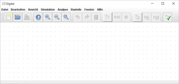
- You should now see an „empty circuit“ in Digital (see Abbildung 1).
- There are several areas in the menu bar, these will be used in the following:
- File selection: New, Open, Save
- Zoom: Auxiliary dialog, Zoom in, Zoom out, Fit in
- Undo, Redo, Delete
- Start simulation, start until stop signal, stop
- Gate step modes
- Test execution
Below the menu bar is the workspace, which is a grid of gray dots.
Step-by-step 2: Creating an input and an output
As a start, a simple circuit with one input and one output shall be created
To do this, go to
Components. There you will find all the necessary components. For the time being, we only need inputs/outputs. These are located underIO. First selectInput- You will then see the component marked with a mint-colored circle. Elements circled in mint are always marked for moving in the program Digital. Click on any position in the workspace
- Then insert an
outputto the right of the input. Here we will introduce another variant for inserting components. Click onView » Tree view of components(orF5). A column with the different components is then displayed on the left. The output is located in this column under IO. This can be inserted into the workspace by drag and drop. - Both components can be connected with a line. A line can be started from any grid point by left clicking and ended by
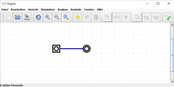
Esc. A line can also be start or end at an output (red dot on a component: •) or an input (red dot on a component: •). - With this, the first simple circuit is already created (see Abbildung 2). The circuit can be activated by pressing the start icon
►. If you have forgotten the connection or if there is another error, an error message appears. After confirming this error, the faulty component is highlighted in red. - When a circuit is started, input components can be actuated. Existing other components will then also become active. You should test this by pressing the input. Then stop the simulation by pressing the Stop icon
■(stopping by►is also possible). The circuit can now be edited again.
Step-by-step 3: Change properties and extend circuitry
- The previous circuit is now further expanded. The aim now is a circuit input and output of 8 bits. How a bit/byte is defined is shown in the chapter number systems. The trivial solution would be to multiply the existing circuit with
<Ctrl>+<A>,<Ctrl>+<C>,<Ctrl>+<V>. But here we will present another variant, which transports the 8 bits via a data bus. A data bus is defined as lines that belong together. - To do this, right-click on the input to change its properties. The number of
data bitsshould now be increased to 8 and thedesignationto A. The changes must be confirmed withOK. - When the circuit is started, the somewhat cryptic error message appears:
1 bit is required, but 8 bits were found. Affected are: Line out.Additionally, the connection line and the output are marked. We forgot to set the output to 8 bits… - To solve this, again not the trivial variant (right click „ Change) shall be described, but a slightly different possibility:
- mark everything with
<Ctrl>+<A>. - Right click
- Change
Data Bits. Although this option is grayed out because the components have different values there. By clicking on the box□next to data bits, the option can be changed.
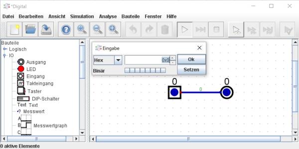
- If the circuit is started now, a 0 appears over input, line, and output (see Abbildung 3).
- A (left)click on the input no longer changes the value directly, but opens an input window. In this window, numbers can be entered as decimal values (
10), binary values (0b10), hexadecimal values (0x10), or octal values (010). Pressing Line break (<↵>) accepts the value and closes the input window. Clicking Shift + New Line (<↑><↵>) accepts only the value. The cursor keys up/down allow the displayed value to be counted up/down.
Homework
- Determine the hexadecimal values for 070, 64, and 0b01100110.
- Change the output to a decimal value display and determine the decimal values for 064, 0x70, and 0b10011001.


