0 Tools
In the following, you will learn about two simulation tools. With these tools, you can reconstruct circuits and display their voltages and currents. This is particularly important for understanding circuits with operational amplifiers and transistors.
Why two simulation tools?
- For learning and understanding, it is important on the one hand that you get a feeling for how currents and voltages are set in circuits.
- On the other hand, you should practice using professional tools that enable high-quality simulations.
The former tools should allow simple visualization. The latter tools are usually a bit more difficult to handle, but allow more complex circuits and more detailed measurements. For high-quality simulation, you will use the free program TINA TI in the following. Illustration of concepts is made possible by Falstad's online simulation.
0.1 First steps in TINA TI
TINA is a SPICE (Simulation Program with Integrated Circuit Emphasis) program from Texas Instruments. With this program, you can simulate electronic circuits and display the time sequences. This is very useful for learning and testing, but can also simulate more realistic setups.
- Introduction to TINA TI 0 - Explanation of TINA, download and installation
-
The free version of the program is already very comprehensive. You can find it as follows (recommended is link 1!):
- TINA TI Download on this wiki (login via university account)
- in the ILIAS course
- Download (a bit cumbersome) via the TI page
Manual
An English manual can be found at here in the wiki.
A German manual is only available for the full version.Exercises
Please install TINA TI.
Here are some tips:- For „User Name“ and „Company Name“ you can enter pseudonyms (
Hinz&Kunz,HHN). - Select
European (DIN)at „Select schematic symbol set you to want to use“. - All file paths should fit as recommended.
The following introduction is based on videos in German. For the English introduction please refer to the first lecture available in ILIAS.
Alternatively, a nice introduction is also available on yoututbe from Professor Fiore.
- Introduction to TINA TI 1 - Structure of TINA TI, first circuitry
-
Learning Objectives
By the end of this section, you will be able to:
- be familiar with the various component bars in TINA TI,
- insert and rotate components and their descriptions,
- edit component values,
- draw connections.
Tasks
- Rebuild the circuit from the video in TINA TI.
- Change the following additional values:
- Output value of the voltage source: $10 V$
- Size of resistor R1: $20k$
- Size of resistor R2: $30k$
- Introduction to TINA TI 2 - Output of values and debugging
-
Learning Objectives
By the end of this section, you will be able to:
- perform the „Electrical Rule Check“ and use it for debugging,
- measure output values such as voltages and currents,
- use multimeters in TINA TI to measure voltages and currents,
- insert current measuring points correctly,
Tasks
- Rebuild the circuit from the video in TINA TI.
- Instead of the Current Arrow, use the Ammeter and instead of the Voltmeter, use the Voltage Pin.
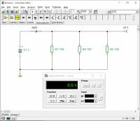
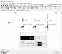
Are there any differences when you use them? - Imagine you want to build a small circuit with 3 light-emitting diodes and wonder how much the voltage of the two 1.5V batteries will drop.
- Build the simplified parallel circuit 1 (see picture).
The internal resistance of the battery should be 500mOhm (property „Internal Resistance“).- What voltage/current is measured?
- How large is the current through one strand?
- Optional: To do this, reconstruct the parallel circuit 2 (see picture). The internal resistance of the battery should be maintained.
- What voltage/current is measured?
- What is the current through one strand?
Solution:Battery voltage 2.97V, battery current for variant 1: 74.07mA, battery current for variant 2: 67.76mA
- Introduction to TINA TI 3 - Even more errors and many diagrams
-
Learning Objectives
By the end of this section, you will be able to:
- correct the most common errors in the simulation yourself,
- display time sequences of signals,
- work with the cursor in diagrams, separate curves, and insert a legend,
- create and evaluate curves over temperature and other variables,
- create a structured simulation with a title.
You can find the template file under Tipps für TINA TI
Tasks
- You can find exercises for this video in the following chapter
- Tips for TINA TI
-
- Avoid nodes directly on the output of a component.
- The following keyboard shortcuts make Tina easier to use:
<Strg>+<R>: Right-rotate a selected component.<Strg>+<L>: Left-rotate a selected component.<Strg>+<Space>: Switch to connection mode (wire).<Strg>+<C>,<Strg>+<V>: Copy, Paste.<Strg>+<Z>,<Strg>+<Y>: Undo, Redo.
- Please use the template file template_cd_v01.tsc when starting a simulation.
- General tips
-
- Use rule checks available with simulation tools, such as the „Electrical Rule Check“ (ERC)..
Rule checks show errors and warnings. If there are errors, the simulation will not run. If there are warnings, it will run, but there are unclear areas in the circuitry. - Avoid unclean identifiers and text. I.e. try to write the text so that it is directly legible (not overlapping, similar alignment).
- Always specify a reference potential (ground).
0.2 Online Circuit Simulator
- Introduction to Online Circuit Simulator - Explanation, Example
-
In addition to TINA TI, another simulation tool is used in this course: The Online Circuit Simulator.
This tool can help to better understand the currents and voltages in different circuits. The program displays the current flow and the applied voltage in animated form. Under „Circuits“ and „Operational amplifiers (OPVs)“ you will find various circuits that are useful for this course.There is an English Manual available from the University of Memphis. The Source Code of the simulator can be found on GitHub.
Tasks
Familiarize yourself with the Online Circuit Simulator from Falstad
- first with the embedded example on the right
- If the circuit is too small, click on
Edit»Center Circuit
If only part of the available space is taken up by the circuit after this, refreshing the browser window (<Ctrl>+R) or editing directly on the Online Circuit Simulator Homepage will help. - Most circuits on the wiki are initially stopped. The simulation can be started by pressing RUN/Stop.
- Check the change in the current flow results when different switches are activated.
- Change the resistor values by double-clicking on the respective resistor.
- further examples of an equivalent voltage source (Thévenin's theorem) and equivalent current source (Norton's theorem)
- Search in
Circuits»Basics»Thévenin Theorem - At the bottom left of the window, you will see two running graphs of the currents and voltages of the two circuits.
Click with the right mouse button on one of the diagrams and selectCombine. The curves should now be directly on top of each other - Move the mouse over one of the two voltage sources.
The respective voltage/current curve is highlighted.
Are both curves on top of each other? - Do the same for the equivalent current source (Norton theorem).
0.3 Further Simulation Tools
In addition to the tools explained so far, there are other simulation tools - which we do not use in the courses. Some of them are briefly summarized here with their limitations.
| Name | Focus | Limits | Commercial Product |
|---|---|---|---|
| Tina TI | Simulation of analog circuits (e.g. amplifier circuits) | function limited in the commercial product also the simulation of mixed digital-analog circuits is possible | Designsoft Tina |
| MPLab Mindi | Simulation of transient transitions (z.B. DCDC-converter) | Number of nodes < 150 (approx.) | SIMETRIX / SIMPLIS |
| LTSpice | broadly based Simulation | flat, long learning curve (unusual key mapping) | - |
0.4 Literature recommendations
For self-study, I recommend the following literature.
| Title | Author | Short description |
|---|---|---|
| Operationsverstärker | J. Federau | German textbook with illustrative approaches. Accessible via university network or VPN. |
| OP Amp Applications Handbook | very nice and detailed textbook of the manufacturer Analog Devices, „Freeware“, online available. | |
| Handbook of Operational Amplifiers Application | A similar nice handbook is available from the competitor Texas Instruments | |
| Electronic Circuits | U. Tietze, Chr. Schenk, E. Gamm | very detailed reference book. Accessible via university network or VPN. Additionally there is a collection of exercises |

