Lab01 - Resistors
Challenge description
An automotive engineer is testing the electrical system of a passenger car. The vehicle has a 12 V battery, interior lighting, a temperature sensor, and a rear window heater. During vehicle development, the engineer must verify electrical components using resistance measurements, Ohm's law, series and parallel circuits, Kirchhoff's laws, and the behavior of a non-linear load.
Resistance is defined by voltage and current:
$$ R = \frac{U}{I} $$
A constant supply voltage is available for the experiment. This raises the following questions:
- How will the different values of $U$ and $I$ influence $R$?
- How can the set of nodes help to understand the current flow?
- How will the voltage be affected from nonlinear resistors?
To answer these questions, different circuits are investigated: the Mesh-set, Set of nodes and a light bulb circuit for nonlinear resistors.
Resistance measurement
Background Information
Procedure for resistance measurement:
* Set the measuring device to resistance measurement
* Connect the resistance to be measured to the corresponding sockets on the measuring device (the measuring device sockets labeled COM and $\Omega$
* Read the measured value
There are different types of resistance measurement:
* direct resistance measurement
* indirect resistance measurement
The resistances can also be determined by measuring the current/voltage.
Ohm's law: In an electrical circuit, the current increases with increasing voltage and decreases with increasing resistance.
$$ I=\frac{U}{R} $$
Experimental Tasks
Direct resistance measurement
Determine the nominal and measured values of the resistance for $R_{\rm 1}$ (brown, green, orange), $R_{\rm 2}$ (yellow, violet, red), $R_{\rm 3}$ (red, violet, red) and the incandescent lamp $R_{\rm L}$. Also measure the approximate resistance $R_{\rm K}$ of your body from your right to your left hand.
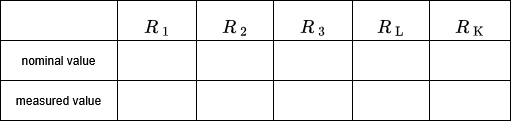
How do you explain the deviation between $R_{\rm L,nominal}$ and $R_{\rm L,meas}$?
What consequences can $R_{\rm K}$ have?
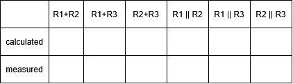
Now determine the series and parallel connections of resistors $R_{\rm 1}$, $R_{\rm 2}$ and $R_{\rm 3}$.
Specify the formulas used:
$R_{\rm serial}$ =
$R_{\rm parallel}$ (= $R_{\rm a}$ || $R_{\rm b}$) =
Indirect resistance measurement
Build the measuring circuit shown in figure 1 for each of the three resistors and set the voltage on the power supply to $~{\rm 12} ~{ V}$.
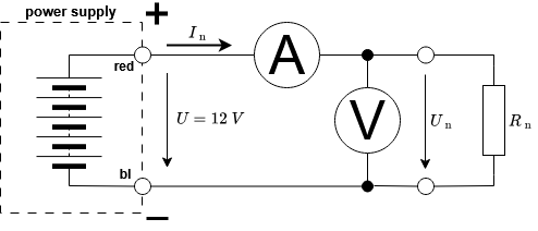 Fig. 1: Indirect resistance measurement
Measure $U_{\rm n}$ [V] and $I_{\rm n}$ [mA]. Calculate $R_{\rm n}$ [k$\Omega$] from these values.
Fig. 1: Indirect resistance measurement
Measure $U_{\rm n}$ [V] and $I_{\rm n}$ [mA]. Calculate $R_{\rm n}$ [k$\Omega$] from these values.

Test Questions - Resistors
Mesh set
In every closed circuit and every mesh of the network, the sum of all voltages is zero!
Set the voltage on the power supply to $12~\rm V$ and measure this voltage precisely using a multimeter. Set up the measuring circuit shown in figure 2.

Fig. 2: Mesh-set
Add the voltage arrows and measure $U$, $U_{\rm 1}$ und $U_{\rm 2}$:

What is the mesh set here?
Check the formula with the measured values:
The resistors $R_{\rm 1}$ and $R_{\rm 2}$ connected in series form a voltage divider. What is the ratio between the voltages $U_{\rm 1}$ and $R_{\rm 2}$?
$$ \frac{U_1}{U_2} = $$
Set of nodes
At each junction point, the sum of all incoming and outgoing currents is equal to zero!
Set the voltage on the power supply to $12~\rm V$ and measure the voltage accurately with a multimeter. In the first step, set up the measuring circuit shown in figure 3:
 Fig. 3: Node-set circuit 1
Draw the arrows for the directions of currents $I_{\rm 1}$ and $I_{\rm 2}$ in figure 4. The DC current measurement range must be set on both multimeter using the rotary switch. Then measure currents $I_{\rm 1}$ and $I_{\rm 2}$ and enter the measured values in table 5.
Fig. 3: Node-set circuit 1
Draw the arrows for the directions of currents $I_{\rm 1}$ and $I_{\rm 2}$ in figure 4. The DC current measurement range must be set on both multimeter using the rotary switch. Then measure currents $I_{\rm 1}$ and $I_{\rm 2}$ and enter the measured values in table 5.
 Fig. 4: Node-set circuit 2
What is the relationship between currents $I_{\rm 1}$ and $I_{\rm 2}$?
$$ \frac{I_1}{I_2} = $$
Switch the power supply back on and measure the current $I$. Enter its value in table 5.
Fig. 4: Node-set circuit 2
What is the relationship between currents $I_{\rm 1}$ and $I_{\rm 2}$?
$$ \frac{I_1}{I_2} = $$
Switch the power supply back on and measure the current $I$. Enter its value in table 5.

Determine the node set for node K and check its validity.
Using the measured values for resistors $R_{\rm 1}$, $R_{\rm 2}$, and $R_{\rm 3}$, calculate the total resistance $R_{\rm KP}$:
Using the calculated value $R_{\rm KP}$, check the measured value of the total current:
$$ I=\frac{U}{R_{KP}} = $$
Voltage divider as voltage source
The voltage divider shown in figure 5 is in an unloaded state, as the entire current supplied by the power supply flows through the resistors $R_{\rm 1}$ and $R_{\rm 2}$ connected in series. A resistor parallel to $R_{\rm 2}$ loads the voltage divider.
Set the voltage on the power supply to $12 ~\rm V$ and measure the exact voltage with a multimeter. Set up the measuring circuit shown in figure 5.
For the connected load $R_{\rm L}$ = ${\rm 10} ~{\rm k\Omega}$, the voltage divider represents a voltage source. Like any voltage source, it has a source voltage (also called the original voltage) $U_{\rm 0}$ and an internal resistance $R_{\rm i}$. The internal resistance of a voltage divider considered as a voltage source results from the parallel connection of the divider resistors $R_{\rm 1}$ and $R_{\rm 2}$:
$$ R_i = R_1 || R_2 = \frac{R_1\cdot R_2}{R_1+R_2} $$
Use the measured values of resistors $R_{\rm 1}$ and $R_{\rm 2}$ to calculate the internal resistance $R_{\rm i}$ of the voltage source:
$$ R_i = $$
$$ U_0 = $$
The power $P_{\rm 0}$ supplied by the power supply can be calculated using the following equation:
$$ P_0 = U\cdot I_1$$
The power consumed by the load resistance can be determined using the following formula:
$$ P_L = R_L\cdot {I_2}^2$$
 Fig. 5: Voltage divider
Draw the equivalent voltage source of the voltage divider:
What would be the value of $U_{\rm 2}$ without $R_{\rm L}$?
$$ U_{2, zero} = $$
Calculate $U_{\rm 2,L}$ and $I_{\rm 2}$ for $R_{\rm L}$ = ${\rm 10} ~{\rm k\Omega}$ using the values of the equivalent voltage source: (Provide formulas!)
$$ U_{2L} : $$
$$ I_2 : $$
Check the values by measuring:
$$ U_{2L, Meas} : $$
$$ I_{2, Meas} : $$
Check the values using Kirchhoff's rules:
(Provide formulas!)
$$ U_{2L} : $$
$$ I_2 : $$
Nonlinear resistors
All resistors examined so far are linear resistors, for which the characteristic curve $I=f(U)$ is a straight line, s. figure 6.
The resistance value of a linear resistor is independent of the current $I$ flowing through it or the applied voltage $U$.

Fig. 6: Characteristic curve of a linear resistor
With nonlinear resistors, there is no proportionality between current and voltage. The characteristic curve of such a resistor is shown in figure 7. With these resistors, we talk about static resistance ($R$) and dynamic (or differential) resistance ($r$). The static resistance is determined for a specific operating point: at a specific voltage, the current is read from the resistance characteristic curve.
The calculation is performed according to Ohm's law:
$$ R = \frac{U}{I} $$
The differential resistance around the operating point is calculated from the current difference caused by a change in the applied voltage:
$$ r = \frac{\Delta U}{\Delta I} $$

Fig. 7: Characteristic curve of a nonlinear resistor
A light bulb is examined as an example of a nonlinear resistor. Set up the measuring circuit shown in figure 8.

Fig. 8: Measuring circuit light bulb
Set the voltage on the power supply to the voltage values from table 6. Measure the corresponding current values and enter them in table 6.

Create the characteristic curve $I = f(U)$, s. figure 9

Fig. 9: Characteristic curve light bulb
Calculate the static resistance $R$ at the operating point $U = \rm 7.0 ~V$:
Calculate the dynamic resistance $r$ at the operating point $U = \rm 7.0 ~V$:
Compare the values with the values from table 1 (direct resistance measurement)