Exercise 2.7.7 Simplifying Circuits (exam task, about 8% of a 60-minute exam, WS2020)
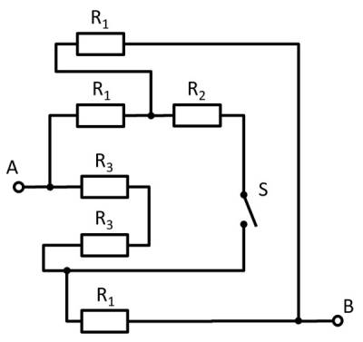
Given is the adjoining circuit with
$R_1=10 ~\Omega$
$R_2=20 ~\Omega$
$R_3=5 ~\Omega$
and the switch $S$.
1. Determine the total resistance $R_{\rm eq}$ between A and B by summing the resistances with the switch $S$ open.
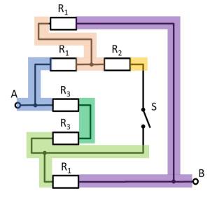
- How can the circuit be better represented or pulled apart?
- The switch should be replaced by an open wire in this case.
For this purpose, the individual branches can be highlighted in color and interpreted as a „conductive rubber band“.
This results in:
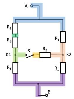
Thus $R_3$ and $R_3$ can be combined to $R_{33} = 2 \cdot R_3 = R_1$, yielding a left and a right voltage divider.
Now it is visible that in the left and right voltage divider, the same potential is at the respective branch, or at the node K1 (green) and K2 (pink).
Thus, the total resistance can be calculated as $R_{\rm eq} = (2 \cdot R_1)||(2 \cdot R_1)$.
However, by symmetry, nodes K1 and K2 can also be short-circuited. Thus, $R_{\rm eq} = 2 \cdot \left( R_1||R_1 \right)$ also holds.
2. What is the total resistance when switch $S$ is closed?
So the resistance remains the same.


