Exercise E4
Charging Capacitors
(written test, approx. 16 % of a 60-minute written test, WS2022)
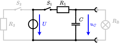
The circuit shown in the following is used to control the brightness when turning on a small light bulb.

The circuit contains a voltage source $U=12 ~\rm{V}$, a switch $S_1$, a resistor of $R_1=20 ~\Omega$ and a capacitor of $C=100 ~\rm{µF}$.
The switch $S_2$ to an additional consumer $R_2$ will be considered to be open for the first tasks. At the moment $t_0=0 ~\rm{s}$ the switch $S_1$ is closed, the voltage across the capacitor is $u_c (t_0 )=0 ~\rm{V}$.
1. First do not consider the light bulb – it is not connected to the RC circuit.
Calculate the point of time $t_1$ when $u_c (t_1)=0.5\cdot U$.
So, here only R_1 and C gives the time constant: $\tau = R_1 \cdot C$
The following formula describes the time course of $u_C(t)$ which has to be $u_c (t_1)=0.5\cdot U$: \begin{align*} u_c (t) = U \cdot (1- e^{t/\tau}) = 0.5\cdot U \end{align*} It has to be rearranged to $t$ \begin{align*} (1- e^{t/\tau}) &= 0.5 \\ e^{t/\tau} &= 0.5 \\ t/\tau &= ln(0.5) \\ t &= \tau \cdot ln(0.5) \\ t &= R_1 \cdot C \cdot ln(0.5) \end{align*}
2. Calculate the overall energy dissipated by $R_1$ while charging the capacitor $0 ~\rm{V}$ to $12 ~\rm{V}$.
3. Now, consider the light bulb as a resistor of $R_\rm B=20 ~\Omega$, and ignore again the left side ($S_2$ is open).
The voltage across the capacitor is again $0 ~\rm{V}$ at the moment $t_0=0 ~\rm{s}$ when the switch $S_1$ is closed.
Calculate the voltage $u_c (t_2)$ across the capacitor at $t_2=1 ~\rm{ms}$ after closing the switch.
Hint: To solve this, first create an equivalent linear voltage source from $U$, $R_1$, and $R_\rm B$.
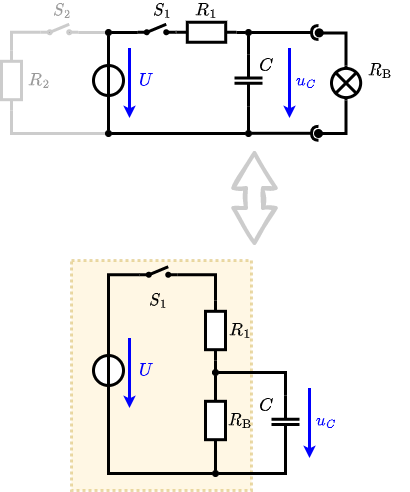
An equivalent linear voltage source can be given with $U$, $R_1$, and $R_\rm B$ as seen in yellow.
Therefore, the voltage of the equivalent linear voltage source is: $U_s = U \cdot {{R_\rm B}\over{R_1 + R_\rm B}} = 1/2 \cdot U$
The internal resistance is given by substituting the ideal voltage source with its resistance ($=0 ~\Omega$, short-circuit).
\begin{align*}
R_i &= R_1 || R_\rm B \\
&= 10 ~\Omega
\end{align*}
\begin{align*} u_c (t_2) &= U_s \cdot (1- e^{t_2/(R_i\cdot C)}) \\ &= {{1}\over{2}} \cdot U \cdot (1- e^{1~\rm{ms}/(10 ~\Omega \cdot 100 ~\rm{µF})}) \end{align*}
4. Explain (without calculation) how the situation in 3. would change once also $S_2$ is closed from the beginning on.
On an alternative view, one can try to create an equivalent linear voltage source again. Then, the internal resistance is given by substituting the ideal voltage source is again short-circuiting $R_2$.