This is an old revision of the document!
3. Combinatorical Logic
introductional example
The combinatorial logic shown in <impref pic1> enables to output distinct logic values for eacht logic input. When you change the input nibble you can see that the the correct number appears on the 7-segment-display. By clicking onto the bits of the input nibble, you can change the number.
Tasks:
- Which output $Y_0$ … $Y_6$ is generated from the input nibble
1000? Which from1001? - Is the output only depending on the input? Is there a dependance on the histroy?
3.1 Combinatorical Circuit
Up to now, we looked onto simple logic circuits. Thes are relatively easy to analyze and synthesize (=develop). The main question in this chapter is: how can we set up and optimize logic circuits?
In the following we have a look onto combinatorical circuits. These are generally logic circuits with
- $n$ inputs $X_0$, $X_1$, … $X_{n-1}$
- $m$ outputs $Y_0$, $Y_1$, … $Y_{m-1}$
- no “memory”, that is: a given set of input bits results in a distinct output
They can be description by
- truth table
- boolean formula
- hardware description language
The ladder one is not in the focus of this course.
The applications range:
- (simple) half/full adder
- digital comparators (logic circuit to compare 2 values)
- Multiplexer / demultiplexer
- Arithmetic logic units in microcontrollers and processors
- much more
3.1.1 Example
In order to understand the synthesis of a combinatoric logic we will follow a step-by-step example for this chapter.
Imagine you are working for a company called “mechatronics and robotics”. One costumer wants to have an intelligent switch as input device connected to a microcontroller for controlling an oven. For this project “Therm-o-Safety” he needs a combinatoric logic:
- The intelligent switch has 4 user selectable positions: $1$, $2$, $3$, $4$
- Additionally there are 2 non-selectable positions for the case of failure.
- The output $Y=1$ will activate a temperature monitoring.
- The temperature monitoring has to be active for $3$ and $4$ and in case of a major failure. A major failure is for example, when the switch position is unclear. In this case the input of the combinatorial circuit is “ON”.
- There are no other cases of inputs.
This requirements are put into a truth table:
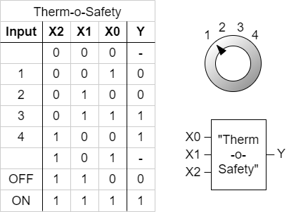
figure 2 shows one implementation of this requirements. The inputs 001 … 011 represent the inputs $1$…$4$. The cases of failure are coded with 110 and 111.
The output $Y$ is activated as requested. For the two combinations 000 and 101 there is no output value defined. Depending on the requierements for a project these shall either better be 0 or 1 or the output of these does not matter. We had this “does not matter” before: the technical term is “I don't care”, and it is written as a - or a x.
By this, we have done the first step in order to syntesize the requested logic.
3.1.2 Sum of Products
Now, we want to investigate some of the input combinations (= lines in the truth table). At first, we have a look onto the input combination 011, where the output has to be $Y=1$.
If this input combination would be the only one for the output of $Y=1$, the following could be stated:
“$Y=1$ (only) when the $X_0$ is $1$ AND $X_1$ is $1$ AND $X_2$ is $0$ ”. It can also be re-arranged to:
“$Y=1$ (only) when the $X_0$ is $1$ AND $X_1$ is $1$ AND $X_2$ is not $1$ ”.
This statement is similar to $X_0 \& X_1 \& \overline{X_2}$. The used conjuntion resuts only in $1$, when all inputs are $1$. The negation of $X_2$ takes account of the fact, that $X_2$ has to be $0$.
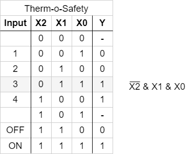
figure 3 shows the boolean expression for ths combination. In figure 4, this boolean expression is converted into a struction with logic gates.
With the same idea in mind, we can have a look for the other combinations resulting in $Y=1$. These are the combinations 100 and 111:
- For
100The statement would be: “$Y=1$ (only) when the $X_0$ is $0$ AND $X_1$ is $0$ AND $X_2$ is $1$”. Similary to the combination above this leads to: $\overline{X_0} \& \overline{X_1} \& {X_2}$. - For
111, the boolean expression is ${X_0} \& {X_1} \& {X_2}$.
Note!
- Each row in a truth table (=one distinct combination) can be represented by a minterm or maxterm
- A minterm is the conjunction (AND'ing) of all inputs, where unter certain instances a negation have to be used
- In a minterm an input variable with
0has to be negated, in order to use it as an input for the AND.
e.g. $X_0 = 0$ AND $X_1 = 1 \quad \rightarrow \quad \overline{X_0} \& X_1$
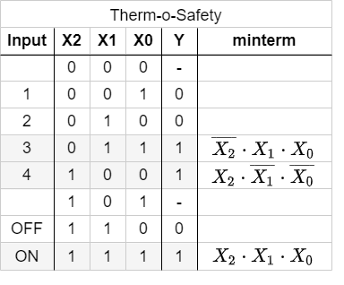
In figure 5 all minterms for $Y=1$ are shown. The figure 6 depicts all the logic circuits for the three minterms. These lead to the outputs $Y'$, $Y''$, and $Y'''$.
For the final step we have to combine the single results for the minterms. The output has to be $1$ when at least one of the minterms is $1$. Therefore, the minterms have to be connected disjunctive:
\begin{align*} Y &= & Y' & \quad + & Y'' & \quad + & Y''' \\ Y &= & (X_0 \& X_1 \& \overline{X_2}) & \quad + & (\overline{X_0} \& \overline{X_1} \& {X_2}) & \quad + & ({X_0} \& {X_1} \& {X_2}) \\ \end{align*}
This leads to the logic circuit shown in figure 7. Here, you can input the different combinations by clicking onto the bits of the input nibble.
Note!
- The disjunction of the minterms is called sum of products, SoP, disjunctive normal form or DNF.
- When all inputs are used in each of the minterms the normal form is called full disjunctive normal form
- When snytesizing a logic circuit by sum of procucts, all 'don't care' terms outputing $0$.
We have seen, that the sum of products is one tool to derive a logic circuit based on a truth table. Alternatively it is also possible to insert an intermediate step, where the logic formula is simplified.
In the following one possible optimization is shown:
\begin{align*} Y &= & (X_0 \& X_1 \& \overline{X_2}) & \quad + & (\overline{X_0} \& \overline{X_1} \& {X_2}) & \quad + & ({X_0} \& {X_1} \& {X_2}) & \quad | \text{associative law} \\ Y &= & (\overline{X_0} \& \overline{X_1} \& {X_2}) & \quad + & (X_0 \& X_1 \& \overline{X_2}) & \quad + & ({X_0} \& {X_1} \& {X_2}) & \quad | \text{associative law } \\ Y &= & (\overline{X_0} \& \overline{X_1} \& {X_2}) & \quad + & ((X_0 \& X_1) \& \overline{X_2}) & \quad + & (({X_0} \& {X_1}) \& {X_2}) & \quad | \text{distributive law } \\ Y &= & (\overline{X_0} \& \overline{X_1} \& {X_2}) & \quad + & ((X_0 \& X_1) \& (\overline{X_2} + {X_2})) & & & \quad | \text{complementary element} \\ Y &= & (\overline{X_0} \& \overline{X_1} \& {X_2}) & \quad + & (X_0 \& X_1) & & & \quad | \text{complementary element} \\ \end{align*}
3.1.3 Product of Sums
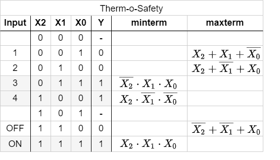
In the sub-chapter befor we had a look onto the combinations which generates an output of $Y=1$ by means of the AND operator. Now we are investigating the combinations with $Y=0$. Therefore, we need an operator, which results in $0$ for only on distinct combination.
The first combination to look for is 001.
If this input combination would be the only one for the output of $Y=0$, the following could be stated:
“$Y=0$ (only) when the $X_0$ is $1$ AND $X_1$ is $0$ AND $X_2$ is $0$ ”.
With having the duality in mind (see cpt. The Set of Rules) the opposite is also true:
“$Y=1$ when $X_0$ is $0$ OR $X_1$ is $1$ OR $X_2$ is $1$ ”
This is the same like: $\overline{X_0} + X_1 + X_2$
The booleand operator we need hiere is the OR-operator.
Simmilarly, the combinations 010 und 110 can be transformed. Keep in mind, that this time we are looking for a formula with results in $0$ only for the given one distinct combination.
Note!
- A maxterm is the disjunction (OR'ing) of all inputs, where unter certain instances a negation have to be used.
- In a maxterm an input variable with $1$ has to be negated, in order to use it as an input for the OR.
The figure 8 shows all the maxterms for the Therm-o-Safety example.
The formulas of figure 8 can again be transformed into gate circiuts (figure 9). Here, only for the inputs '001', '010', '110' one of the outputs $Y'$, $Y''$ or $Y'''$ is $0$.
When these intermediate outputs $Y'$, $Y''$, $Y'''$ are used as an input for an AND-gate the resultin output will get $0$ when at least one of the intermediate outputs are $0$. This results in another way to synthesize the Therm-o-Safety (see figure 10)
Note!
- The disjunction of the maxterms is called products of sum, PoS, conjunctive normal form or CNF.
- The products of sum is the DeMorgan dual of the sum of products.
3.2
3.2.1 The Karnaugh Map
Exercise 3.1.x Further Querstions
- compare the results with the output given here (the output $y$ can be changed by clicking onto it)