This is an old revision of the document!
3. Combinatorical Logic
introductional example
The combinatorial logic shown in <impref pic1> enables to output distinct logic values for eacht logic input. When you change the input nibble you can see that the the correct number appears on the 7-segment-display. By clicking onto the bits of the input nibble, you can change the number.
Tasks:
- Which output $Y_0$ … $Y_6$ is generated from the input nibble
1000? Which from1001? - Is the output only depending on the input? Is there a dependance on the histroy?
3.1 Combinatorical Circuit
Up to now, we looked onto simple logic circuits. Thes are relatively easy to analyze and synthesize (=develop). The main question in this chapter is: how can we set up and optimize logic circuits?
In the following we have a look onto combinatorical circuits. These are generally logic circuits with
- $n$ inputs $X_0$, $X_1$, … $X_{n-1}$
- $m$ outputs $Y_0$, $Y_1$, … $Y_{m-1}$
- no “memory”, that is: a given set of input bits results in a distinct output
They can be description by
- truth table
- boolean formula
- hardware description language
The ladder one is not in the focus of this course.
The applications range:
- (simple) half/full adder
- digital comparators (logic circuit to compare 2 values)
- Multiplexer / demultiplexer
- Arithmetic logic units in microcontrollers and processors
- much more
3.1.1 Example
In order to understand the synthesis of a combinatoric logic we will follow a step-by-step example for this chapter.
Imagine you are working for a company called “mechatronics and robotics”. One costumer wants to have an intelligent switch as input device connected to a microcontroller for controlling an oven. For this project “Therm-o-Safety” he needs a combinatoric logic:
- The intelligent switch has 4 user selectable positions: $1$, $2$, $3$, $4$
- Additionally there are 2 non-selectable positions for the case of failure.
- The output $Y=1$ will activate a temperature monitoring.
- The temperature monitoring has to be active for $3$ and $4$ and in case of a major failure. A major failure is for example, when the switch position is unclear. In this case the input of the combinatorial circuit is “ON”.
- There are no other cases of inputs.
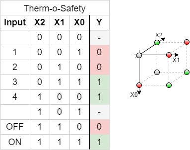
This requirements are put into a truth table:
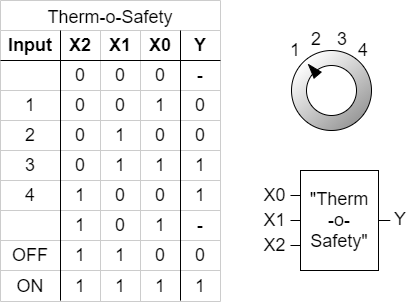
figure 2 shows one implementation of this requirements. The inputs 001 … 011 represent the inputs $1$…$4$. The cases of failure are coded with 110 and 111.
The output $Y$ is activated as requested. For the two combinations 000 and 101 there is no output value defined. Depending on the requierements for a project these shall either better be 0 or 1 or the output of these does not matter. We had this “does not matter” before: the technical term is “I don't care”, and it is written as a - or a x.
By this, we have done the first step in order to syntesize the requested logic.
3.1.2 Sum of Products
Now, we want to investigate some of the input combinations (= lines in the truth table). At first, we have a look onto the input combination 011, where the output has to be $Y=1$.
If this input combination would be the only one for the output of $Y=1$, the following could be stated:
“$Y=1$ (only) when the $X_0$ is $1$ AND $X_1$ is $1$ AND $X_2$ is $0$ ”. It can also be re-arranged to:
“$Y=1$ (only) when the $X_0$ is $1$ AND $X_1$ is $1$ AND $X_2$ is not $1$ ”.
This statement is similar to $X_0 \cdot X_1 \cdot \overline{X_2}$. The used conjuntion resuts only in $1$, when all inputs are $1$. The negation of $X_2$ takes account of the fact, that $X_2$ has to be $0$.
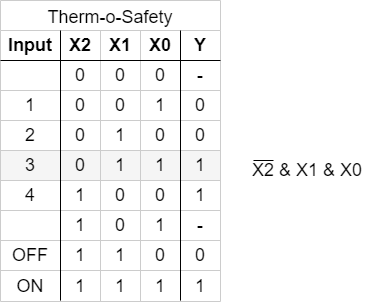
figure 3 shows the boolean expression for ths combination. In figure 4, this boolean expression is converted into a struction with logic gates.
With the same idea in mind, we can have a look for the other combinations resulting in $Y=1$. These are the combinations 100 and 111:
- For
100The statement would be: “$Y=1$ (only) when the $X_0$ is $0$ AND $X_1$ is $0$ AND $X_2$ is $1$”. Similary to the combination above this leads to: $\overline{X_0} \cdot \overline{X_1} \cdot {X_2}$. - For
111, the boolean expression is ${X_0} \cdot {X_1} \cdot {X_2}$.
Note!
- Each row in a truth table (=one distinct combination) can be represented by a minterm or maxterm
- A minterm is the conjunction (AND'ing) of all inputs, where unter certain instances a negation have to be used
- In a minterm an input variable with
0has to be negated, in order to use it as an input for the AND.
e.g. $X_0 = 0$ AND $X_1 = 1 \quad \rightarrow \quad \overline{X_0} \cdot X_1$
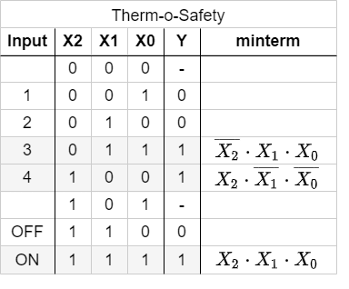
In figure 5 all minterms for $Y=1$ are shown. The figure 6 depicts all the logic circuits for the three minterms. These lead to the outputs $Y'$, $Y''$, and $Y'''$.
For the final step we have to combine the single results for the minterms. The output has to be $1$ when at least one of the minterms is $1$. Therefore, the minterms have to be connected disjunctive:
\begin{align*} Y &= & Y' & \quad + & Y'' & \quad + & Y''' \\ Y &= & (X_0 \cdot X_1 \cdot \overline{X_2}) & \quad + & (\overline{X_0} \cdot \overline{X_1} \cdot {X_2}) & \quad + & ({X_0} \cdot {X_1} \cdot {X_2}) \\ \end{align*}
This leads to the logic circuit shown in figure 7. Here, you can input the different combinations by clicking onto the bits of the input nibble.
Note!
- The disjunction of the minterms is called sum of products, SoP, disjunctive normal form or DNF.
- When all inputs are used in each of the minterms the normal form is called full disjunctive normal form
- When snytesizing a logic circuit by sum of procucts, all 'don't care' terms outputing $0$.
We have seen, that the sum of products is one tool to derive a logic circuit based on a truth table. Alternatively it is also possible to insert an intermediate step, where the logic formula is simplified.
In the following one possible optimization is shown:
\begin{align*} Y &= & (X_0 \cdot X_1 \cdot \overline{X_2}) & \quad + & (\overline{X_0} \cdot \overline{X_1} \cdot {X_2}) & \quad + & ({X_0} \cdot {X_1} \cdot {X_2}) & \quad | \text{associative law} \\ Y &= & (\overline{X_0} \cdot \overline{X_1} \cdot {X_2}) & \quad + & (X_0 \cdot X_1 \cdot \overline{X_2}) & \quad + & ({X_0} \cdot {X_1} \cdot {X_2}) & \quad | \text{associative law } \\ Y &= & (\overline{X_0} \cdot \overline{X_1} \cdot {X_2}) & \quad + & ((X_0 \cdot X_1) \cdot \overline{X_2}) & \quad + & (({X_0} \cdot {X_1}) \cdot {X_2}) & \quad | \text{distributive law } \\ Y &= & (\overline{X_0} \cdot \overline{X_1} \cdot {X_2}) & \quad + & ((X_0 \cdot X_1) \cdot (\overline{X_2} + {X_2})) & & & \quad | \text{complementary element} \\ Y &= & (\overline{X_0} \cdot \overline{X_1} \cdot {X_2}) & \quad + & (X_0 \cdot X_1) \\ \end{align*}
3.1.3 Product of Sums
In the sub-chapter before we had a look onto the combinations which generates an output of $Y=1$ by means of the AND operator. Now we are investigating the combinations with $Y=0$. Therefore, we need an operator, which results in $0$ for only on distinct combination.
The first combination to look for is 001.
If this input combination would be the only one for the output of $Y=0$, the following could be stated:
“$Y=0$ (only) when the $X_0$ is $1$ AND $X_1$ is $0$ AND $X_2$ is $0$ ”.
With having the duality in mind (see cpt. The Set of Rules) the opposite is also true:
“$Y=1$ when $X_0$ is $0$ OR $X_1$ is $1$ OR $X_2$ is $1$ ”
This is the same like: $\overline{X_0} + X_1 + X_2$
The booleand operator we need hiere is the OR-operator.
Simmilarly, the combinations 010 und 110 can be transformed. Keep in mind, that this time we are looking for a formula with results in $0$ only for the given one distinct combination.
Note!
- A maxterm is the disjunction (OR'ing) of all inputs, where unter certain instances a negation have to be used.
- In a maxterm an input variable with $1$ has to be negated, in order to use it as an input for the OR.
The figure 8 shows all the maxterms for the Therm-o-Safety example.
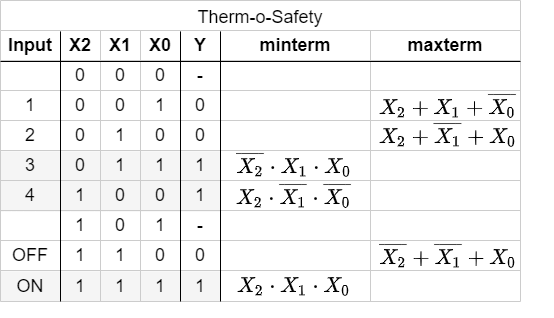
The formulas of figure 8 can again be transformed into gate circiuts (figure 9). Here, only for the inputs '001', '010', '110' one of the outputs $Y'$, $Y''$ or $Y'''$ is $0$.
When these intermediate outputs $Y'$, $Y''$, $Y'''$ are used as an input for an AND-gate the resultin output will get $0$ when at least one of the intermediate outputs are $0$. This results in another way to synthesize the Therm-o-Safety (see figure 10)
Also the products of sum can be simplified:
\begin{align*} Y &= & (\overline{X_0} + X_1 + X_2) & \quad \cdot & ({X_0} + \overline{X_1} + X_2) & \quad \cdot & (\overline{X_0} + \overline{X_1} + X_2) \\ &= & ... \\ Y &= & (\overline{X_0} + X_1 + X_2) & \quad \cdot & (\overline{X_0} + \overline{X_1}) \\ \end{align*}
This result $Y$ by the sum of products is different compared to the result in product of sums:
- product of sums: $Y = (\overline{X_0} \cdot \overline{X_1} \cdot {X_2}) + (X_0 \cdot X_1)$
- sum of products: $Y = (\overline{X_0} + X_1 + X_2) \cdot (\overline{X_0} + \overline{X_1})$
In this case these resuls cannot be transformed into each other with the means of boolean rules.
Note!
- The disjunction of the maxterms is called products of sum, PoS, conjunctive normal form or CNF.
- When all inputs are used in each of the minterms the normal form is called full conjunctive normal form
- When snytesizing a logic circuit by sum of procucts, all 'don't care' terms outputing $1$
- The products of sum is the DeMorgan dual of the sum of products if there are no don't care terms. Otherwise the resuls cannot be transformed into each other with the means of boolean rules.
3.2 Karnaugh Map
3.2.1 Introduction with example
For our therm-o-safety example we found two possible gate logics which can produce the required output. We also have seen, that optimizing the terms (i.e. the min- or maxterms) is often possible. But ip to now we do not know how we can find optimum implementation.
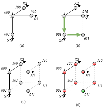
For this, we try to interpret the inputs of our example as dimensions in a multidimensional space. The three input variables $X_0$, $X_1$, $X_2$ span a 3-dimensional space. The point 000 is the origin of this space. The three combinations 001, 010, 100 are onto the $X_0$-, $X_1$-, and $X_2$-axis, respectively. The other combinations can be reached by adding the
Exercise 3.1.x Further Querstions
- compare the results with the output given here (the output $y$ can be changed by clicking onto it)