Übungsblatt 3
Bitte laden Sie das aufgefüllte PDF in ILIAS hoch.
Details, Tipps und Tools zum Ausfüllen und Einfügen von Bildern finden Sie unter:
Tools für Lehr/Lern-Veranstaltungen
| Name | Vorname | Matrikelnummer |
|---|---|---|
| $\quad\quad\quad\quad\quad\quad\quad\quad$ | $\quad\quad\quad\quad\quad\quad\quad\quad$ | $\quad\quad\quad\quad\quad\quad\quad\quad$ |
| |
Exercise 2.1.1 Diode at higher frequencies

In your company “HHN Mechatronics & Robotics” you have built a single-ended rectifier to rectify a sinusoidal measuring signal of ($f=200kHz$, amplitude $\hat{U} = 5.0V$, output resistance of the sensor $R_q = 10k$). For this purpose you built a simple circuit with the “Si rectifier diode” $D=1N5400$ and a smoothing capacitor with $C=10pF$. As measuring instrument you used an oscilloscope (Rigol DS1000E). The circuit is drawn in the adjacent sketch.
Your colleague has already pointed out to you that at high frequencies some diodes get a problem with rectification. You also noticed this when measuring the setup and looking at the oscilloscope…
Write down the expected signal curve before the respective simulation. Note that you must consider a steady-state system in the simulation!
- Find in the Instruction of the oscilloscope the values of the input impedance, which are needed in the circuit for the input resistance $R_E$ and the input capacitance $C_E$.
Replicate the circuit in using the information from TINA TI above (Circuit 1). Take into account the input impedance of the oscilloscope, as shown in the sketch.
Simulate circuit 1 with the specified signal. Briefly describe the expected and measured signal waveforms. - Try tuning the capacitance of capacitor $C$ to get the expected rectified value. What do you find?
- Since something seems to be funny, you want to debug the circuit, that is, determine the error. To do this, you could use the generic approach to debugging (in German). Or you break down the unclear system to a minimum. Specifically, you build a modified circuit (Circuit 2):
- the sensor is replaced by a function generator (same frequency and amplitude, but $R_q = 50 \Omega$),
- the smoothing capacitor $C$ is replaced by an open lead (so it is no longer present)
- Simulate circuit 2 with the signal given so far. Briefly describe the expected and measured signal characteristics.
- Now take another step back and try to get a little more current flowing across the diode. In circuit 2, the current was limited by $R_E$ and thus the diode was not yet operating above $U_S=0.7V$. The idea now in Circuit 3 is to also switch the input resistor to $R_E = 50 \Omega$ (this is possible on some oscilloscopes). The rest of circuit 3 is the same as circuit 2. Simulate circuit 3 with the signal given so far.
- Now you seem to be getting closer to the problem. You vary input resistance to $R_E = 500 \Omega$ (Circuit 4)
Simulate circuit 4 with the given signal. Briefly describe the expected and measured signal waveforms. - Your colleague tips you that the progression (see diagram on the right) is typical of
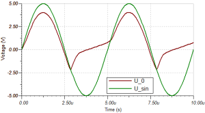
- A reverse recovery time $t_{rr}$ that is too large. This is reproduced in Tina via the transit time $TT$.
- an excessive junction capacity (junction capacity $C_j$ or diode capacity $C_D$).
- These values can be changed in Tina TI by the following procedure: Double-click on the diode » click on
…at Type » search for the mentioned values.
You now want to analyze how the reverse bias and the junction capacitance affect the voltage curve (for circuit 4).
Simulate and describe the voltage curve if- on the one hand the reverse bias is reset to $0s$ or
- on the other hand, the junction capacitance is reset to $0F$.
describe the voltage waveform.
- Instead of diode $D=1N5400$, choose diode $D=1N4148$ and simulate again circuit 3 and circuit 1.
Now how does the voltage waveform behave and why?

Exercise 2.1.2 Calculating a series resistor for a diode
You want to drive a red light-emitting diode on a voltage source of $U_s = 5.0 V$ with a current of $I_D = 20 mA$. On the Internet, you have found a voltage drop of $U_D = 2.3 V$ for red LEDs. Now you want to know which resistor from the E12 series (available to you) is the correct one.
- Draw the circuit of the LED with series resistor and plot the voltages.
- What must be the value of the series resistor $R_V$ to give the voltage drop $U_S$ above?
- In the red LED datasheet TLUR6400, find the relationship between forward voltage (“Forward Voltage”) and forward current (“Forward Current”). What voltage drop $U_D$ can be determined from this for $I_D = 20 mA$ and what is the correct series resistance?
\ \ \ \ \ \ \ \ \ \ \ \ \ \ \.
- Briefly compare the different results considering the E12 series.
\
\ \ \ \ \ \ \ \ \ \ \ \ \ \
Exercise 2.1.3 Z-diode as voltage reference
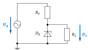
In a voltage reference circuit, a Z-diode enables - despite a fluctuating input voltage - an output voltage to be kept relatively constant. In the simplest case, a circuit as shown on the right can be used for this purpose. The following quantities are to be used for the task:
- Source voltage $U_S=7.0 ... 13.0V$ (e.g. via sinusoidal input voltage with $f = 50 Hz$),
- series resistor $R_V=1.0k\Omega $
- load resistor $R_L=10k\Omega $
- Z-diode $D_Z$ as $BZX84C6V2$ ($U_Z = 6.2 V$)
An ideal (Z) diode would be assumed to hold the breakdown voltage $U_Z$ at all reverse currents $I_S$.
This is to be checked for the real diode.
- Model the circuit in Tina TI and insert a picture of the circuit.
- Compare the progression of $U_L$ to $U_S$. In particular, measure the maximum and minimum values of $U_L$.
- Change the load resistance to $R_L=1.0k\Omega $ and perform the same comparison of $U_L$ to $U_S$ again.
- How can the difference be explained?
Exercise 2.1.4 Calculating the differential resistance of a diode

The differential resistance $r_D$ of a diode was already described in the chapter. This is necessary if a diode is to be simulated via a simplified diode model (voltage source + resistor + ideal diode, if applicable). In figure 1, see the differential conductance $g_D={{1}\over{r_D}}$ as the local slope at the desired operating point. Calculate the differential resistance $r_D$ at forward current $I_D=15 mA$ for room temperature ($T=293K$) and $m=1$ from Shockley's equation: ${I_F = I_S(T)\cdot (e^{\frac{U_F}{m\cdot U_T}}-1)}$ with $U_T = \frac{k_B \cdot T}{e}$. To do this, first calculate the general formula for the differential resistance $r_D$.
Steps:
1. First, simplify Shockley's equation for $U_F >> U_T$
2. Find a formula for $\frac {d I_F}{d U_F}$.
3. Again, replace part of the result with $I_F$ and rotate the fraction to calculate the differential resistance by $r_D = \frac {d U_F}{d I_F}$.
As a result, you should now have $r_D = \frac {d U_F}{d I_F} = \frac {m \cdot U_T}{I_F}$.
4. Calculate $r_D$.