Dies ist eine alte Version des Dokuments!
0. Tools
In the following you will learn about two simulation tools. With these tools you can reconstruct circuits and display their voltages and currents. This is particularly important for understanding circuits with operational amplifiers and transistors.
Why two simulation tools?
- For learning and understanding, it is important on the one hand that you get a feeling for how currents and voltages are set in circuits.
- On the other hand, you should practice using professional tools that enable high-quality simulations.
The former tools should allow simple visualization. The latter tools are usually a bit more difficult to handle, but allow more complex circuits and more detailed measurements. For high-quality simulation, you will use the free program TINA TI in the following. Illustration of concepts is made possible by Falstad's online simulation.
0.1 First steps in TINA TI
TINA is a SPICE (Simulation Program with Integrated Circuit Emphasis) program from Texas Instruments. With this program you can simulate electronic circuits and display the time sequences. This is very useful for learning and testing, but can also simulate more realistic setups.
- Introduction to TINA TI 0 - Explanation of TINA, download and installation
-
The free version of the program is already very comprehensive. You can find it as follows (recommended is link 1!):
- TINA TI Download on this wiki (login via university account)
- in the ILIAS course
- Download (a bit cumbersome) via the TI page
Manual
An english manual can be found here in the wiki.
A German manual is only available for the full version.Exercises
Please install TINA TI.
Here some tips:- For „User Name“ and „Company Name“ you can enter pseudonyms (
Hinz&Kunz,HHN). - Select
European (DIN)at „Select schematic symbol set you want to use“. - All file paths should fit as recommended.
- Introduction to TINA TI 1 - Structure of TINA TI, first circuitry
-
Goals
After this lesson you should:
- be familiar with the various component bars in TINA TI,
- be able to insert and rotate components and their descriptions,
- be able to edit component values,
- be able to draw connections.
Tasks
- Rebuild the circuit from the video in TINA TI.
- Change the following additional values:
- Output value of the voltage source: $10 V$
- Size of resistor R1: $20k$
- Size of resistor R2: $30k$
- Introduction to TINA TI 2 - Output of values and debugging
-
Goals
After this lesson you should:
- be able to perform the "Electrical Rule Check" and use it for debugging, - measure output values such as voltages and currents, - be able to use multimeters in TINA TI to measure voltages and currents, - be able to insert current measuring points correctly,
Tasks
- Rebuild the circuit from the video in TINA TI.
- Instead of the Current Arrow, use the Ammeter and instead of the Voltmeter, use the Voltage Pin.
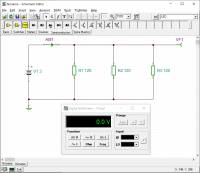
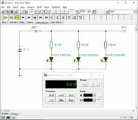
Are there any differences when you use them? - Imagine you want to build a small circuit with 3 light emitting diodes and wonder how much the voltage of the two 1.5V batteries will drop.
- Build the simplified parallel circuit 1 (see picture).
The internal resistance of the battery should be 500mOhm (property „Internal Resistance“).- What voltage/current is measured?
- How large is the current through one strand?
- Optional: To do this, reconstruct the parallel circuit 2 (see picture). The internal resistance of the battery should be maintained.
- What voltage / current is measured?
- What is the current through one strand?
Solution:Battery voltage 2.97V, battery current for variant 1: 74.07mA, battery current for variant 2: 67.76mA
- Introduction to TINA TI 3 - Even more errors and many diagrams
-
Goals
After this lesson you should:
- be able to correct the most common errors in the simulation yourself,
- be able to display time sequences of signals,
- work with the cursor in diagrams, separate curves and insert a legend,
- be able to create and evaluate curves over temperature and other variables,
- be able to create a structured simulation with title.
You can find the template file under Tipps für TINA TI
Tasks
- You can find exercises for this video in the following chapter
- Tips for TINA TI
-
- Avoid nodes directly on the output of a component.
- The following keyboard shortcuts make Tina easier to use:
<Strg>+<R>: Right-rotate a selected component.<Strg>+<L>: Left-rotate a selected component.<Strg>+<Space>: Switch to connection mode (wire).<Strg>+<C>,<Strg>+<V>: Copy, Paste.<Strg>+<Z>,<Strg>+<Y>: Undo, Redo.
- Please use the template file Vorlage_EST.TSC when starting a simulation.
- Generelle Tipps
-
- Nutzen Sie vor bei Simulationstools vorhandene Rule Checks, wie dem „Electrical Rule Check“ (ERC).
Rule Checks zeigen Fehler und Warnungen an. Bei Fehlern wird die Simulation nicht laufen. Bei Warnungen wird sie laufen, aber es gibt unklare Bereiche in der Schalung. - Vermeiden Sie unsaubere Bezeichner und Texte. D.h. versuchen Sie Text so zu schreiben, dass er von leserlich ist (nicht überlappend, gleich ausgerichtet).
- Geben Sie immer ein Bezugspotential (Ground) an.
0.2 Online Circuit Simulator
- Einführung in Online Circuit Simulator - Erklärung, Beispiel
-
Neben TINA TI wird in diesem Kurs ein weiteres Simulationswerkzeug genutzt: Der Online Circuit Simulator.
Dieser kann helfen, die Ströme und Spannungen bei unterschiedlichen Schaltungen besser zu verstehen. Das Programm gibt Stromfluss und anliegende Spannung animiert wieder. Unter „Schaltungen“ » „Operationsverstärker (OPVs)“ finden Sie diverse Schaltungen die für diesen Kurs sinnvoll sind.
Die Landesberufsschule Salzburg hat eine Kurzanleitung zum Online Circuit Simulator erstellt. Der Source Code des Simulators ist auf GitHub zu finden.Aufgaben
Machen Sie sich mit dem Online Circuit Simulator von Falstad vertraut
- zunächst mit dem eingebundenen Beispiel rechts
- Falls die Schaltung zu klein ist, klicken Sie auf
Bearbeiten»Schaltung zentrieren
Falls danach nur ein Teil des verfügbaren Platz von der Schaltung eingenommen wird, hilft eine Aktualisierung des Browserfensters (<Strg>+R) oder eine Bearbeitung direkt auf der Online Circuit Simulator Homepage. - Die meisten Schaltungen im Wiki sind zunächst gestoppt. Die Simulation kann über einen Druck auf
RUN/Stopgestartet werden. - Prüfen Sie welche Änderung sich im Stromfluss über verschiedene Schalterstellungen ergibt
- Ändern Sie die Widerstandswerte über Doppelklick auf den jeweiligen Widerstand
- mit weiteren Beispielen zur Ersatzspannungsquelle (Thévenin-Theorem) und Ersatzstromquelle (Norton-Theorem)
- Suchen Sie unter
Schaltungen»Grundlagen»Thévenin-Theorem - Unten links im Fenster Sehen Sie zwei laufende Diagramme der Ströme und Spannungen der beiden Schaltungen.
Klicken Sie mit der Rechten Maustaste auf eines der Diagramme und wählen SieKombinieren. Die Verläufe sollten nun direkt übereinander liegen - Fahren sie mit der Maus über eine der beiden Spannungsquellen.
Der jeweilige Spannungs-/Stromverlauf wird hervorgehoben.
Liegen beide Kurven übereinander? - Führen Sie das gleiche bei der Ersatzstromquelle (Norton-Theorem) durch
0.3 Weitere Simulationstools
Neben den bisher erklärten Werkzeugen gibt es weitere Simulationstools. Einige davon finden Sie hier mit ihren Limitierungen kurz zusammengefasst.
| Name | Fokus | Limitierungen | kommerzielles Produkt |
|---|---|---|---|
| Tina TI | Simulation von analogen Schaltungen (z.B. Verstärkerschaltungen) | Funktion eingeschränkt im kommerziellen Produkt ist auch die Simulation von gemischt digital-analoge Schaltungen möglich | Designsoft Tina |
| MPLab Mindi | Simulation von transienten Übergängen (z.B. DCDC-Wandler) | Anzahl der Knoten < 150 (ca.) | SIMETRIX / SIMPLIS |
| LTSpice | breit aufgestellt | flache Lernkurve (ungewöhnliche Tastenbelegung) | - |
0.4 Literaturempfehlungen
Zum Selbststudium empfehle ich folgende Literatur.
| Titel | Autor | Kurzbeschreibung |
|---|---|---|
| Operationsverstärker | J. Federau | Lehrbuch mit anschaulichen Ansätzen. Über Hochschulnetz oder VPN einsehbar. |
| OP Amp Applications Handbook | sehr schönes und ausführliches Lehrbuch des Herstellers Analog Devices, „Freeware“, Online einsehbar | |
| Handbook of Operational Amplifiers Application | Ein ähnlich schönes Handbuch gibt es auf vom Wettbewerber Texas Instruments | |
| Halbleiter-Schaltungstechnik | U. Tietze, Chr. Schenk, E. Gamm | sehr ausführliches Nachschlagewerk. Über Hochschulnetz oder VPN einsehbar. Zusätzlich gibt es eine Sammlung von Übungsaufgaben |

