This is an old revision of the document!
Exercise Sheet 1
Please upload the filled PDF in ILIAS.
Details, tips and tools for filling and inserting images can be found at:
Tools für Lehr/Lern-Veranstaltungen
| Name | First Name | Matrikelnumber |
|---|---|---|
| $\quad\quad\quad\quad\quad\quad\quad\quad$ | $\quad\quad\quad\quad\quad\quad\quad\quad$ | $\quad\quad\quad\quad\quad\quad\quad\quad$ |
| |
Exercise 1.1.1 Microphone amplifier I
An amplifier circuit shall amplify a microphone signal in such a way that a loudspeaker ($R_{LS}= 8.0 \Omega$) can be driven. The rms value of the desired voltage across the loudspeaker shall be $U_{RMS,LS} = 10 V$. It is assumed that a sinusoidal signal is to be output. The power is supplied by two voltage sources with $V_{S+} = 15 V$ and $V_{S-} = - 15 V$. For understanding (especially for tasks 2. and 3.), look at the simulation under the subchapter equivalent circuit in chapter “1. amplifier basics”. This example shows a realistic amplifier, but also the idealized current flow can be guessed from this.
- Draw a labelled sketch of the circuit with the amplifier as a black box.
- What power $P$ does the loudspeaker consume?
- From this, how can we determine the rms current $I_{RMS,S}$ of the power supply at which the above desired voltage $U_{RMS,LS}$ is output at the loudspeaker?
- Determine from the previous task the maximum current $I_{max,S}$ for which the two power supplies must be designed at least.
(Note that for simple amplifiers the output current $I_O$ is always less than or equal to the current $I_S$ of the power supply).
Exercise 1.1.2 Microphone amplifier II
A voltage amplifier circuit is given, which shall amplify a microphone signal in such a way that a loudspeaker ($R_{LS}= 8.0 \Omega$) can be driven. Neither amplification nor the desired voltage at the loudspeaker is known. This amplifier circuit is internally protected against overcurrents above $I_{max,amplifier}= 5.0 A$ by a fast fuse. It is known that no overcurrents occur in the allowed voltage operation of $8.0 \Omega$ loudspeakers.
- By what factor does the current change if a $4.0 \Omega$ loudspeaker is used instead of an $8.0 \Omega$ loudspeaker?
- What effect does this have on the fuse?
Exercise 1.1.3 Wheatstone bridge circuit
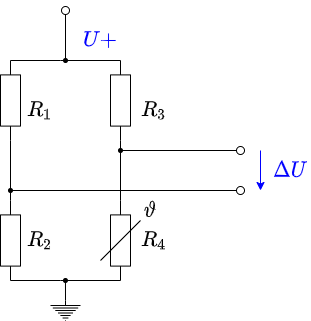
Imagine that you work in the company “HHN Mechatronics & Robotics”. You are developing an IoT system that will be used in a harsh environment and will contain a rechargeable battery. The temperature of the battery must be monitored during operation and charging. If the temperature is too high, charging must be aborted or a warning issued. For the temperature measurement at the housing of the used lithium-ion cell NCR18650 a measuring circuit is to be built up. A suggestion for the circuit is as follows:
- Wheatstone bridge circuit with $R_1 = R_2 = R_3 = R_4 = 1.0k \Omega $.
- Let the resistor $R_4$ be a PT1000 with a temperature coefficient $\alpha = 3850 \frac{ppm}{K}$.
- For the other resistors, to components are chosen, that have an unknown temperature coefficient. According to the data sheet temperature coefficient is within $\alpha = \pm 100 \frac{ppm}{K}$.
- The voltage source of the system generates a voltage of 5V with sufficient accuracy.
- The determined voltage $\Delta U$ is amplified by a factor of 20 through another amplifier circuit, output as $U_{O}$, and further used by an analog-to-digital converter in a microcontroller 1).
A short report is to be created; Tina TI is to be used as the analysis tool. Es ist ein kurzer Bericht zu erstellen; als Analysewerkzeug ist Tina TI zu verwenden.
- Create a problem description.
- Rebuild the circuit in TINA TI and add this here. Take the following hint into account.
Hint
Use a simple resistor for the PT1000 in the simulation. With Tina TI, 27°C (room temperature) is selected as the reference temperature for the temperature curve. For the PT1000, the reference temperature is often 0°C (in practical applications, this should be checked in the data sheet). With Tina TI, the reference temperature can be changed by entering the value 27 under
Temperature [C]in the properties (double-click on Resistor).
- From the data sheet linked above, determine in what range from $T_{min}$ to $T_{max}$ may be charged and what temperature $T_{lim}$ may not be exceeded in any of the states.
- First, for temperature invariant $R_1 = R_2 = R_3 = 1.0k \Omega$ and a temperature variable resistor $R_4$, determine the voltage change $\Delta U$ over the temperature of $-30...70°C$ in TINA TI. To do this, create a plot with $\Delta U$ as a function of temperature.
Read $\Delta U^0 (T_{min})$, $\Delta U^0 (T_{max})$, $\Delta U^0 (T_{lim})$, from the diagram and check the plausibility of the values by calculation.
- Determine $\Delta U$ when the temperature dependence of $R_1$, $R_2$ and $R_3$ is taken into account. To do this, create a suitable diagram with $\Delta U$ as a function of temperature in TINA TI.
At what voltages $U_O (T_{min})$, $U_O (T_{max})$ must the microcontroller intervene and disable charging?
At what value $U_A (T_{lim})$ must a warning be issued?
- Discuss the results