Exercise Sheet 2
Please upload the filled PDF in ILIAS.
Details, tips and tools for filling and inserting images can be found at:
Tools für Lehr/Lern-Veranstaltungen
| Name | First Name | Matrikelnumber |
|---|---|---|
| $\quad\quad\quad\quad\quad\quad\quad\quad$ | $\quad\quad\quad\quad\quad\quad\quad\quad$ | $\quad\quad\quad\quad\quad\quad\quad\quad$ |
| |
Exercise 1.2.1 Conversion of Amplifiers
In the lecture, the different amplifier types were presented as black boxes. Thereby the adjacent picture was used for the input and output quantities and the ideal resistance values were derived. In the following, you are to consider how these can be converted into each other by interconnecting them with other passive, electrical components.
How can the following amplifiers be converted into each other? For each, draw a circuit with the amplifier as shown opposite as a black box.
- Voltage amplifier into current voltage converter
- Current amplifier in voltage current converter
Exercise 1.3.1 Feedback in TINA
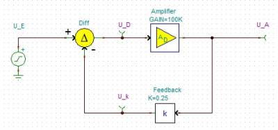
The TINA simulation is generally used to simulate circuit diagrams. In the following, a block diagram of the feedback (see picture) is to be examined. Please download the following file and work on the task contained in it.
file: exercise_1.3.1.tsc
Compare the results with the findings from the chapter feedback!
Exercise 1.3.2 Calculations for negative feedback
For the principle of negative feedback, the adjacent block diagram was given in the script. Here $A_\rm D$ is the so-called differential gain, i.e. the gain of the difference between the input voltage $U_\rm I$ and the feedback voltage.
- Derive the voltage gain $A_\rm V$ as a function of the differential gain $A_\rm D$ and the feedback factor $k$. Note that $A_{\rm V} = {{U_\rm O}\over{U_\rm I}} = f(A_{\rm D}, k)$ and give the derivation.
- What is the voltage gain $A_\rm V$ for an ideal differential gain ($A_\rm D \rightarrow \infty $)?
- Find the voltage gain $A_\rm V$ for feedback $k = 0.001$ with differential gain $A_{\rm D1} = 100'000$ and $A_{\rm D2} = 200'000$.
Real differential amplifiers, more precisely operational amplifiers, are considered in more detail in Chapter 3. Two operational amplifiers of the same type can have noticeably different values in the differential gain, e.g., due to specimen scattering, aging, or temperature drift.
Looking at the result from $A_{\rm D1}$ and $A_{\rm D2}$, what can be said about such a variation of a large differential gain value by, say, $50~\%$?
- State how the voltage gain behaves for the following feedback parameter $k$ with an ideal differential gain and correctly assign the following statements (some are not needed, some are needed more than once):
(A) Positive feedback,
(B) Negative feedback,
(C) Damping,
(D) gain,
(E) voltage gain equals open-loop gain,
(F) $U_{\rm O} = U_{\rm I}$,
(G) $U_{\rm O} = - U_{\rm I}$,
(H) gain equal 0.
- $k < -0$
- $k = 0$
- $0 < k < 1$
- $k = 1$
- $k > 1$
