Übungsblatt 6
Bitte laden Sie das aufgefüllte PDF in ILIAS hoch.
Details, Tipps und Tools zum Ausfüllen und Einfügen von Bildern finden Sie unter:
Tools für Lehr/Lern-Veranstaltungen
| Name | Vorname | Matrikelnummer |
|---|---|---|
| $\quad\quad\quad\quad\quad\quad\quad\quad$ | $\quad\quad\quad\quad\quad\quad\quad\quad$ | $\quad\quad\quad\quad\quad\quad\quad\quad$ |
| |
Exercise 4.2.1 Determination of the transmission behavior of the differential amplifier
In the following, the transfer function of the differential amplifier is to be calculated. To do this, you should follow a few steps.
- Derive the function $U_{\rm O} = f(U_{\rm I1}, U_{\rm I2})$ using superposition.
- To do this, first draw an equivalent circuit in each case.
- Briefly describe the resulting circuit. Which amplification circuit results in each case?
- Then calculate the voltages $U_{\rm O1}$ and $U_{\rm O2}$, and from them $U_\rm O$.
- Determine the function $U_{\rm O} = f(U_{\rm I1}, U_{\rm I2})$ or the resistance values of the circuit shown.
Exercise 4.4.1 Transmission resistance of the current-voltage converter
Derive the gain for the current-voltage converter, i.e. the transmission resistance. Use the procedure that we used for the other amplifiers.
- Draw a circuit with the relevant voltages, currents, resistances, and the operational amplifier
- What are you looking for?
- What is the number of variables
- What is the number of equations required?
- Establishing the known equations.
- Derivation of the transmission resistance.
Exercise 4.5.1 Transfer Conductance of the voltage-current converter
Derive the „amplification“ for the voltage-to-current converter, i.e. the transfer conductance. Use the same procedure that we used for the other amplifiers.
- Draw a circuit with the relevant voltages, currents, resistances, and the operational amplifier.
- What are you looking for?
- What is the number of variables?
- What is the number of necessary equations?
- Establishing the known equations.
- Derivation of the transfer conductance.
Exercise 4.5.2 Earth-related load
If the voltage-current converter is used as a current source, it must be ensured that the load has no contact with the ground.
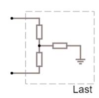
- Draw the voltage-to-current transformer with a load that is in contact with the ground.
- Why is in this case the slope derived above no longer valid as an amplification factor?
- Will the output current be higher or lower in this case?
