This is an old revision of the document!
Exercise 1 : Chargine Capacitors
(written test, approx. 16% of a 60-minute written test, WS2022)
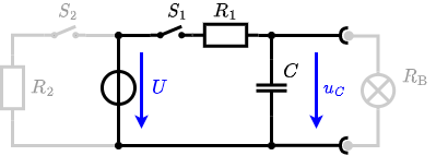
The circuit shown in the following is used to control the brightness when turning on a small light bulb.

The circuit contains a voltage source $U=12 V$, a switch $S_1$, a resistor of $R_1=20 \Omega$ and a capacitor of $C=100 \mu F$.
The switch $S_2$ to an additional consumer $R_2$ will be considered to be open for the first tasks. At the moment $t_0=0 s$ the switch $S_1$ is closed, the voltage across the capacitor is $u_c (t_0 )=0 V$.
1. First do not consider the light bulb – it is not connected to the RC-circuit.
Calculate the point of time $t_1$ when $u_c (t_1 )=0.5\cdot U$.
The following formula describes the time course of $u_C(t)$ \begin{align*} u_c (t) = U \cdot (1- e^{t_1/\tau}) \end{align*} The resulting circuit can again be transformed:

Here, the $U_{24}$ is calculated by $I_{24}$ as the following: \begin{align*} U_{24} &= R_{135} \cdot I_{24} \\ &= ({{U_2}\over{R_1}} - I_4) \cdot R_1||R_3||R_5 \end{align*}
On the right side of the last circuit there is a voltage divider given by $R_{135}$, $R_6$ and $R_7$.
Therefore the voltage between $A$ and $B$ is given as:
\begin{align*}
U_{AB} &= U_{24} \cdot {{R_7}\over{R_6 + R_7 + R_1||R_3||R_5}} \\
&= ({{U_2}\over{R_1}} - I_4) \cdot {{R_7 \cdot R_1||R_3||R_5}\over{R_6 + R_7 + R_1||R_3||R_5}} \\
\end{align*}
For the internal resistance $R_i$ the ideal voltage source is substituted by its resistance ($=0\Omega$, so a short-circuit): \begin{align*} R_{AB} &= R_7 || ( R_6 + R_1||R_3||R_5) \\ \end{align*}
with $R_1||R_3||R_5 = 5 \Omega || 10 \Omega || 10 \Omega = 5 \Omega || 5 \Omega = 2.5 \Omega$:
\begin{align*} U_{AB} &= ({{6.0 V}\over{5.0 \Omega}} - 4.2 \Omega) \cdot {{15 \Omega \cdot 2.5 \Omega}\over{7.5 \Omega + 15 \Omega + 2.5 \Omega}} \\ R_{AB} &= 15 \Omega|| ( 7.5 \Omega + 2.5 \Omega) \\ \end{align*}
2. Calculate the overall energy dissipated by $R_1$ while charging the capacitor $0 V$ to $12 V$.
3. Now, consider the light bulb as a resistor of $R_B=20 \Omega$, and ignore again the left side ($S_2$ is open).
The voltage across the capacitor is again $0 V$ at the moment $t_0=0 s$ when the switch $S_1$ is closed.
Calculate the voltage $u_c (t_2 )$ across the capacitor at $t_2=1 ms$ after closing the switch.
Hint: To solve this, first create an equivalent linear voltage source from $U$, $R_1$ and $R_B$.
4. Explain (without calculation) how the situation in 3. would change once also $S_2$ is closed from the beginning on.