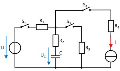
Exercise 5.2.3: Charging and Discharging of RC elements (exam task, ca. 11 % of a 60-minute exam, WS2020)
The circuit shown right is given with the following data:
- $U = 10 ~{\rm V}$
- $I = 4 ~{\rm mA}$
- $R_1 = 100 ~\Omega, R_2 = 80 ~\Omega, R_3 = 50 ~\Omega, R_4 = 10 ~\Omega$
- $C = 40 ~{\rm nF}$
At first, the voltage drop on the capacitor $u_C = 0$, and all switches are open. The switch S1 will be closed at $t = 0$.
1. Determine the time constant $\tau$ for this charging process.
- What equivalent circuit can be found for the mentioned states of the switches?
- What parameter do you need to determine $\tau$?
- The charging current is flown through which component?
2. What is the value of the voltage $u_C(t)$ drop over the capacitor $C$ at $t=10 ~{\rm µs}$?
3. What is the value of the stored energy in the capacitor, when it is fully charged?
4. Determine the new time constant when the switch $S_1$ will be opened and the switch $S_3$ will be closed simultaneously.
5. When the capacitor is completely discharged, all switches will be opened. The switch $S_4$ will be closed at $t= 0$.
What is the voltage $u_C$ at the capacitor C after $t = 1 ~ {\rm µs}$?
- Through the current source there is a continuous flow of electric charge into the capacitor.
- The resistors passed by the current on the way to the capacitor are irrelevant. They only increase the voltage of an ideal current source to guarantee the current.
