Aufgabe 4.5.2: open circuit voltage via superposition (exam task, approx. 12 % of a 60-minute exam, WS2020)
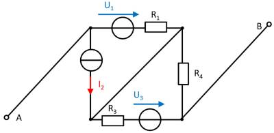
A circuit is given with the following parameters
$R_1=5 ~\Omega$
$U_1=2 ~\rm V$
$I_2=1 ~\rm A$
$R_3=20 ~\Omega$
$U_3=8 ~\rm V$
$R_4=10 ~\Omega$
Determine the open circuit voltage between A and B using the principle of superposition.
- What do the individual circuits look like, by which the effects of the individual sources can be calculated?
Which equivalent resistor must be used to replace a current or voltage source when calculating the individual effects? - Where are the open-circuit voltages applied when looking at the individual components?
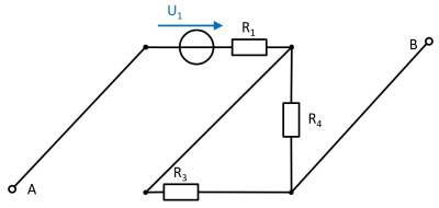
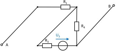
(Voltage) source $U_1$
- substitute the current source $I_2$ with a short-circuit
- substitute the voltage source $U_3$ with an open circuit
The components can be moved in order to understand the circuit s bit better.
For the open circuit, no current is flowing through any resistor. Therefore, the effect is: $U_{AB,1} = U_1$
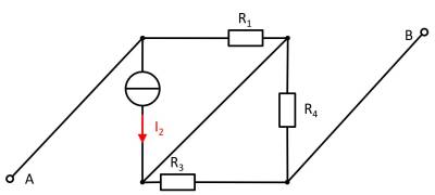
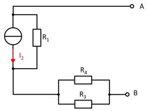
(current) source $I_2$
- substitute the voltage source $U_1$ with an open circuit
- substitute the voltage source $U_3$ with an open circuit
Also here, the components can be shifted for a better understanding:
Here, the current source $I_2$ creates a voltage drop $U_{AB_2}$ on the resistor $R_2$ : $U_{\rm AB,2} = - R_1 \cdot I_2$
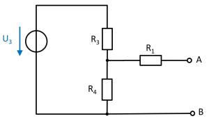
(Voltage) source $U_3$
- substitute the voltage source $U_1$ with an open circuit
- substitute the current source $I_2$ with a short-circuit
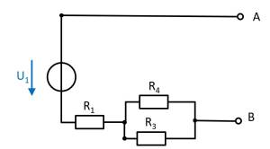
Again, rearranging the circuit might help for an understanding:
In this case, between the unloaded outputs $\rm A$ and $\rm B$ there will be an unloaded voltage divider given by $R_3$ and $R_4$.
On $R_1$ there is no voltage drop since there is no current flow out of the unloaded outputs.
Therefore:
\begin{align*} U_{\rm AB,3} = \frac{R_4}{R_3 + R_4} \cdot U_3 \end{align*}
resulting voltage
\begin{align*} U_{\rm AB} &= U_1 - R_1 \cdot I_2 + \frac{R_4}{R_3 + R_4} \cdot U_3 \\ \end{align*}
