0 Tools
0.1 SimulIDE
You can find the free electronics simulation program SimulIDE in ILIAS under (DE/EN) Software.
Alternatively, the program can also be downloaded from the manufacturer's website. There, a “small contribution” must be entered, which can also be 0€.
In contrast to TINA TI, SimulIDE has a different focus and therefore the following advantages and disadvantages.
Advantages:
- Microcontrollers are simulated well (including Atmel chips). This is not possible in TINA TI.
- The microcontrollers can also be programmed. This means that microcontroller-suitable source files (hex files) can be used.
- Interaction between software and hardware is possible.
Disadvantages:
- Simulation of various electronic components is only implemented in a simplified way (e.g. operational amplifiers or FETs)
- The software is still being heavily developed. This means it is a good idea to use the version specified above in order to avoid compatibility problems.
To get started with SimulIDE, it helps to watch the developer's playlist.
Tips for Using SimulIDE - Configuration
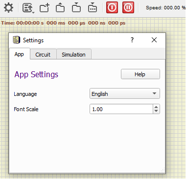
- If the text is displayed too small after opening the program, one of the following approaches may help:
- In SimulIDE, after opening the program, click on the gear icon. Select the
Apptab. There, enter for example 2.0 forFont Scaleand restart the program. - In Explorer:
right-click » Properties » Compatibility » Change high DPI settings » Override high DPI scaling behavior » check the box » select “System”. (if necessary, choose “System (Enhanced)”)
0.2 Microchip Studio
Microchip Studio is a programming environment for creating a microcontroller-suitable source file (hex file) from C or C++.
Installation
Installation Guide
The current version of the program can be found on the Microchip homepage.
- If nothing happens after pressing the
Download Microchip Studiobutton: simply scroll down toDownloads and Documents - With fast internet connections, the web installer can be chosen; with slower connections, the offline installer allows the entire package to be downloaded before installation.
- During installation, only the “AVR” architecture is required.
- “Advanced Software Framework and Example Projects” are not required.
- Depending on the speed of the computer and the internet connection, installation takes about 5 minutes.
- If it is not already installed, Visual Studio will also be installed during installation.
- The question about licenses for the C compiler should be skipped with
Next > - In addition, various device drivers may also be installed. These make it possible to write to the chips using a programming device.
- Afterwards, open Microchip Studio directly so that you can make the first important settings.
for Mac Users
The following procedure is especially recommended for Mac users:
- Open a browser.
- Establish a VPN connection via eduVPN.
- Log in and select a computer.
- Select Mr. Ziegler's image with “uC_PCB” (search for Ziegler)
- Then it will take a little while, because the pool computer now starts the Windows image.
- You can now access a PC with Microchip Studio through your browser.
- Please note that all data is deleted after ending the session.
This means it is a good idea to set up the “U:” drive (“home directory”). Please contact Mr. Ziegler for this.
First Test of the Connection to the AVR-USB-Progi
Carry out the following steps to perform an initial test with the hardware.
- Preparations
- Connect the MiniMEXLE
- to the Progi (black box) via ribbon cable
- to the power outlet via charging cable with the barrel connector
- Open Microchip Studio (for example by pressing the <WIN> key, entering Microchip Studio, and pressing <Return>).
- Download the file 5._menufuehrung.hex.
- After opening the program, connect the Progi to the PC / laptop via USB cable. This step must be done before the following ones!
- The green LED for USB communication should light up on the Progi.
- Enter USB connection
- Without creating a project, go directly to
Tools » Add Target... - In the displayed window, you should select
STK500as the tool in the dropdown menu, which was previously empty. - For the selection of the “Serial Ports”, choose the first available one, e.g.
COM3, and confirm the selection withApply.
If no port is shown here, check whether the connection to the USB-Progi was successful.
If the green LED is lit and the USB cable is connected correctly, refer to the instructions under 4.d.
- First connection attempt
- Select
Tools » Device Programmingin the menu. - Under Tools, select the corresponding USB connection, e.g.
STK500 COM3. - Under Device, you must select
ATmega88; you can enter88and then click the correct value in the dropdown menu. - Under Interface, ISP should now be shown.
- Now press
Apply.
- In case of error:
- If it takes longer after pressing
Apply, the connection did not work. An error messageUnable to connect tool STK500 (COMx)will then be displayed. - You can acknowledge the error message, but after that it takes a few more seconds until the program responds correctly again.
- Then close the
Device Programmingwindow. Go back to point 2 in this guide and try the next serial port.
Remember the number of the port, as this is needed under 3.b. - If all available COM ports have been tested, or none were displayed from the beginning, installing a Virtual COM Port Driver may help. One can be found at FTDI.
- If it works:
- You should now see a bit more in the
Device Programmingwindow. - Before the next steps, connect the MiniMEXLE (= board with display and buttons) to the Progi with the ribbon cable and to the power supply with the barrel connector. Also plug the power supply into an outlet.
- Now press
Readat the top next toDevice Signature. - A hexadecimal number
0x….should appear. Your computer can now establish a connection to the MiniMEXLE for flashing. - In the
Device Programmingwindow, go toMemories. UnderFlash, insert the path to the downloaded file5._menufuehrung.hex. You can also select the path using the…button to the right. - Press
Program - The MiniMEXLE should now display
- Experiment 5 -
Program Menu
and then
Main Level
P1 P2 P3 P4 - This means you have successfully tested the connection and the flashing process
Important Settings
- Use the display of line numbers:
Tools » Options » Text Editor » All languages » General » Line numbers - As soon as you work on the first project: Make sure to disable compiler optimization. This can be done with the following steps:
- Menu
Project » <ProjectName> Properties… » AVR/GNU Compiler » Optimization - The optimization level should be set to
None (-O0)
- I recommend using ATMEL Studio in English. This makes the instructions in this course easier to follow correctly. If you accidentally selected German (e.g. during installation), you can correct it under
Tools » Options » environment » international settings » Language.
Tips
- If the Solution Explorer (display of the files in the project) is not present on the right-hand side, you can find it under
View » Solution Explorer(<CTL>+<ALT>+<L>)
Häufige Fehler
- F_CPU not defined for (z.B. <util/delay.h>) Das beste ist die Frequenz F_CPU im AVR Studio direkt anzugeben:
- Gehe zu Menu:
Projekt » (ProjektName) Eigenschaften » Toolchain » AVR/GNU C Compiler » Symbols - Füge F_CPU=8000000 (bzw. Passende Frequenz) ein
- Das Programm kompiliert nicht TWSR not found : Falls Sie einen modernen AVR Chip nutzen (z.B. 328PB) so kann dieser mehrere SPI und I2C Schnittstellen haben. Damit haben sich bei diesem Target auch die Register- und Interruptvektornamen geändert. Statt TWSR ist dann TWSR0 oder TSWR1 zu verwenden - je nach gewünschtem Pin. Dies ist am einfachsten über defines der fehlerhaften Namen, also
#define TWSR TWSR0usw. - Beim Flashen der realen Hardware über
Tools » Device Programmingfinde ich im Tool nur “Simulation”, aber kein STK500. Versuchen Sie zunächst über Tools » Add tagret… STK500 und den entsprechenden Serial Port zu wählen. Falls Ihr Rechner mehrere USB Ausgänge hat, müssen Sie diese (COM1…COMx) beim Programmieren ausprobieren. - Beim Flashen der realen Hardware erhalte ich “Erasing device failed”, “Error status received: Got 0xc9, expected 0x00 (An unknown command was sent)“.
- Steht bei Device Programming das Interface auf ISP? Falls nicht kann dies die Ursache sein. Das Programming geschieht immer mittels ISP.
- Hat das USB-Kabel/Progi/Adapterplatine/Kabel ein Problem? Probieren Sie eine andere Variante der Komponenten durch
- Mein Chip hat keinen Speicherplatz mehr bzw Ich erhalte ein 'Memory Overflow' Fehler Falls Sie Daten statt im SRAM im EEPROM speichern wollen, so können Sie das Befehlswort “PROGMEM” nutzen. Details dazu finden Sie z.B. auf der Seite von Microchip
- Mein Programm scheint irgendwo nicht weiter zu kommen. Dies kann verschiedene Gründe haben:
- Endlosschleife
- Speicherüberlauf im RAM: sobald die Speicherauslastung des RAM über ca 75% steigt, sind Probleme wie spontane Resets bei Bearbeiten von Pointern, Arrays, Strings oder Structs wahrscheinlich. Die kann über Debugging herausgefunden werden (entweder mit Steppen mit Debugger oder Ausgabe von Werten nach jeder Zeile).
I2C
- Auf den I2C Leitungen ändert sich nichts, obwohl der IC etwas ausgeben sollte:
- Überprüfen Sie die Pullup-Widerstände: Sind welche verbaut? Welche Größe haben diese? (typisch: 10kOhm). Wenn keine Verbaut sind, so wechselt das Signal nur zwischen 0V niederohmig und 0V hochohmig. Dies ist am Oszilloskop nicht zu unterscheiden.
- Ist ein hochohmiger Widerstand $R_L$ entlang der Leitungen verbaut? Falls ja erzeugt dieser einen Spannungsteiler mit dem Pullup-Widerstand. Wenn $R_L$ groß ist, so liegt zwischen $R_L$ und Pull-up fast die Versorgungsspannung an.
- Der Master soll Daten vom Slave empfangen, aber hängt sich manchmal auf Im “Master Receiver Mode” muss der Master das Ende der Kommunikation dem Slave mitteilen. Dazu muss beim Lesen der Daten TWEA = 0 gesetzt werden. Ansonsten kann es sein, dass der Slave meint er müsse noch Daten senden. Das kann unter Umständen dazu führen, dass der Slave die Datenleitung SDA am Ende der Kommunikation auf Low legt und damit den I2C stört.
0.3 MEXLE GitLab
Installation der Software auf Ihrem Rechner
- Laden Sie Git von folgender Seiter herunter: https://git-scm.com/download/win » “Standalone Installer”
Git bietet die Möglichkeit mit dem GitLab Server der Hochschule oder mit GitHub in Kontakt zu treten - Installieren Sie das Git (alle mit “Ok” bzw “Weiter” bestätigen)
- Laden Sie TortoiseGit von folgender Seite herunter: https://tortoisegit.org/download/
totroiseGit bindet den Explorer direkt an die Services des Git an. Damit ist Git direkt in den Explorer eingebunden. - Installieren Sie das TortoiseGit (alle Hinweise mit “Ok” bestätigen)
Anmeldung beim MEXLE GitLab
- Melden Sie sich bei GitLab mit den Hochschul-Credentials an: https://git.mexle.org/
- Gehen Sie zu
User settings»Preferences»Password:
z.B. über folgenden Link: https://git.mexle.org/-/user_settings/password/edit

- Geben Sie ein Passwort mit mindestens 16 Zeichen ein und merken Sie sich dieses Passwort. Dieses Passwort ermöglicht die Authentifizierung auf GitLab.
Bitte nutzen Sie ein neues Passwort!
Installation der Software auf Ihrem Rechner
Die Abfolge ist wie folgt:
- Erst müssen Sie sich in GitLab anmelden
- Dann müssen Sie einem Betreuer per Mail bescheid geben (Prof. Fischer, Ralf Ziegler) , damit dieser Sie zum Projekt zuordnet
- Erst dann sind einem Projekt zugewiesen und können die folgenden Punkte durchführen.
- Gehen Sie in den (Windows) Explorer und legen Sie einen neuen Ordner für die Vorlesung an, z.B.
MikrocontrolleroderElektronik Labor - Klicken Sie mit der rechten Maustaste auf den Ordner, um in das Kontextmenü zu kommen.
Wählen Sie dortGit Clone…aus.

- Im erscheinenden GitClone Fenster sollten Sie Folgendes eingeben:
- als URL:
https://git.mexle.org/[Fach]/[Semester].git
also z.B.https://git.mexle.org/mikrocontroller/26ss.gitoderhttps://git.mexle.org/elektronik/26ss.gitfür das Sommersemester 2026 - als Directory sollte der ausgewählte Ordner eingetragen sein
- Klicken Sie nun auf
Ok

- Im Anschluss sollten Sie eine Fehlermeldung erhalten, da noch das Passwort fehlt.
Hier ist nun das vorher gewählte Passwort einzugeben.
Dies müssen Sie auch nur einmalig machen. - Der Download sollte nun klappen und es sollten alle Ordner heruntergeladen werden
Upload / Commit von Dateien
Das Hochladen und Ändern von Dateien bei Git wird als “Commit” bezeichnet. Diese Nomenklatur wird auch im Folgenden genutzt.
Im Folgenden wird ein Upload beschrieben; über einen Commit können aber auch Dateien gelöscht werden.
- Rechtsklick auf den übergeordneten Ordner »
Git Commit -> “main” …

- Falls eine Fehlermeldung erscheint, siehe nächstes Kapitel
- Im folgenden Fenster ist nun einiges einzutragen:
- Tragen Sie unbedingt einen Text unter
Messageein, ansonsten ist kein Upload möglich!
Schreiben sie einen Text, welcher die Änderungen beschreibt. - Im unteren Teil sind die zu ändernden Dateien zu markieren.
Entweder Sie wählen die Dateien einzeln aus, oder Sie wählen z.B.All. - Zum Commit an den Server wählen Sie am Button unten
▼aus und dortCommit & Push

- Bestätigen Sie nun den Commit über Druck auf den Button
Commit & Push
- Überprüfen Sie, ob der Commit erfolgreich war durch einen Blick auf die Homepage des Projekts.
Hinweise und Mögliche Fehler
- Für Abschlussarbeiten und studentischen Projekte:
- Da diese häufig mehr als 100 MB hochladen, sollten Sie nicht
https://git.mexle.org/...nutzen, sondern:
http://git.mexle.te.hs-heilbronn.de/.... - In diesem Fall müssen Sie im Hochschulnetz befinden (z.B. per eduVPN).
- Fragen Sie bei mir (Tim Fischer) nach, welches Git Repository für Sie das passende ist.
fatal: detected dubious ownership in repository at […] is on a filesystem that does not record ownership
Das Problem ist, das der Ordner auf einem Laufwerk liegt, welches keine Benutzerzuordnung erlaubt (z.B. ein USB-Stick) .
Die Lösung wird gleich mitgeliefert:- Rechtsklick im Explorer auf den entsprechenden Ordner (z.B. 24WS) »
Open Git Bash here» Es öffnet sich eine Text-Konsole - Fügen Sie Folgendes ein
git config --global --add safe.directory D:/GitLab/elektronik/25WS(ändern Sie ggf.elektronikinmikrocontrollerund das Semester) und bestätigen Sie mit Return
git did not exit cleanly (exit code 1)
Das Problem ist, dass ihr lokale Datenbank nicht mehr aktuell ist und sie zunächst die Datenbank vom Server herunterladen müssen (“Pull”).- Generell hilft hier erst zu Pull'en dann zu Commit&Push'en